PRODUCT LITERATURE Lennox Industries Inc. Dallas, Texas INSTALLATION INSTRUCTIONS GWB8-262E-2 GWB8-245E-2 GWB8-299E-2 GWB8-280E-2 GAS FIRED BOILER RETAIN THESE INSTRUCTIONS FOR FUTURE REFERENCE These instructions must be affixed on or adjacent to the boiler. ! WARNING Improper installation, adjustment, alteration, service, or maintenance can cause injury or property damage. Refer to this manual. For assistance or additional information consult a qualified installer, service agency, or the gas supplier.
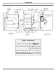
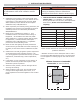
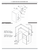
1 - DIMENSIONS Figure 1 - Dimensions Table 1 - Dimensions DIMENSIONS (INCH.) BOILER MODEL NUMBER FLUE DIAMETER “A” WIDTH GWB8-245E-2/GWB8-262E-2 7 27½ GWB8-280E-2/GWB8-299E-2 7 30¾ Add 5½” to height for vent Damper.
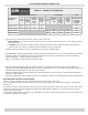
2 - BOILER RATINGS AND CAPACITIES Table 2 - Ratings and Capacities † NATURAL GAS (2) BOILER MODEL NUMBER (1) † Input (3) Mbh Heating Capacity (3) Mbh NET AHRI RATING Water, (3) Mbh † PROPANE GAS AFUE (2) HIGH ALTITUDE INPUT (3) Mbh INPUT (3) Mbh HEATING CAPACITY (3) Mbh NET AHRI RATING Water, (3) Mbh HIGH ALTITUDE INPUT (3) Mbh INTERMITTENT IGNITION WITH VENT DAMPER GWB8-262E-2 262.5 220 191 236 83.9 GWB8-299E-2 299 251 218 269 83.7 GWB8-245E-2 245 206 179 220 83.
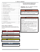
3 - TABLE OF CONTENTS KEEP THIS MANUAL NEAR BOILER RETAIN FOR FUTURE REFERENCE 1 - Dimensions .................................................... 2 2 - Ratings And Capacities .................................... 3 3 - Table of Contents............................................ 4 4 - Installation Procedure ..................................... 5 IMPORTANT: Read the following instructions COMPLETELY before installing!! 5 - Ventilation & Combustion Air ............................
4 - INSTALLATION PROCEDURE ! WARNING ! WARNING Improper installation, adjustment, alteration, service or maintenance could result in death or serious injury. Fire hazard. Do not install boiler on combustible flooring or carpeting. Failure to follow these instructions could result in death or serious injury. 1. FOR INSTALLATION ON NON-COMBUSTIBLE 1. Installation must conform to the requirements of the FLOORS ONLY - For installation on combustible flooring special base must be used.
5 - VENTILATION & COMBUSTION AIR Provide combustion air and ventilation air in accordance with the section “Air for Combustion and Ventilation,” of the National Fuel Gas Code, ANSI Z223.1/NFPA 54, or Sections 8.2, 8.3 or 8.4 of Natural Gas and Propane Installation Code, CAN/CSA B149.1, or applicable provisions of local building codes. • All Outdoor Air. Provide permanent opening(s) communicating directly or by ducts with outdoors. A. Two Permanent Opening Method.
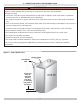
6 - CONNECTING SUPPLY AND RETURN PIPING WARNING ! Burn or Scald Hazard. Discharge line shall be installed to relief valve outlet connection to avoid burns, scalding, or water damage due to discharge of steam and/or hot water during operation. Discharge line shall: • connect to relief valve outlet and piped down to safe point of disposal.
6 - CONNECTING SUPPLY AND RETURN PIPING Verify clean water supply is available to water inlet valve. Install sand strainer when water supply is from a well or pump. ! WARNING Burn and scald hazard. Safety relief valve could discharge steam or hot water during operation. Install discharge piping per these instructions. Install hot water boiler above radiation level or as required by Authority having jurisdiction install low water cutoff device at time of installation.
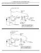
6 - CONNECTING SUPPLY AND RETURN PIPING Figure 4 - Typical Hot Water Piping Figure 5 - Chilled Water Piping 9
6 - CONNECTING SUPPLY AND RETURN PIPING Bypass Piping Required For High Mass (Large Water Content) Systems Figure 6 - BYPASS PIPING - CIRCULATOR ON SUPPLY Figure 7 - BYPASS PIPING - CIRCULATOR ON RETURN 10
7 - CHIMNEY AND VENT PIPE CONNECTION ! WARNING Boiler and venting installations shall be performed by a qualified expert and in accordance with the appropriate manual. Installing or venting boiler or other gas appliance with improper methods or materials may result in serious injury or death due to fire or to asphyxiation from poisonous gases such as carbon monoxide with is odorless and invisible.
7 - CHIMNEY AND VENT PIPE CONNECTION ! WARNING Boiler and venting installations shall be performed by a qualified expert and in accordance with the appropriate manual. Installing or venting boiler or other gas appliance with improper methods or materials may result in serious injury or death due to fire or to asphyxiation from poisonous gases such as carbon monoxide with is odorless and invisible. ! WARNING 5.
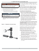
8 - VENT DAMPER OPERATION Figure 8 - Vent Damper Installation Figure 9 - Vent Damper Placement Annually check vent damper and all flue product carrying areas of appliance, with particular attention given to deterioration from corrosion or other sources. If you see corrosion or other deterioration, contact your heating contractor for repairs. Check vent damper operation as follows: • When boiler is off, check vent damper positions indicator points to closed position, Figure 10.
9 - GAS SUPPLY PIPING • Pressure test over 1/2 psig (3.5 kPa). Disconnect boiler and its individual gas shutoff valve from gas supply system. ! CAUTION WHAT TO DO IF YOU SMELL GAS • Do not try to light any appliance. • Pressure test at 1/2 psig (3.5 kPa) or less. Isolate boiler from gas supply system by closing manual gas shutoff valve. • Do not touch any electrical switch; do not use any phone in your building.
10 - ELECTRICAL WIRING ! WARNING Electrical shock hazard. Turn OFF electrical power supply at service panel before making electrical connections. Failure to do so could result in death or serious injury. NOTICE Label all wires prior to disconnection when servicing controls. Wiring errors can cause improper and dangerous operation. Verify proper operation after servicing.
11 - WIRING DIAGRAMS Figure 12 - Integrated High Limit Electronic Ignition Control (240008781) ! WARNING Modification, substitution or elimination of factory equipped, supplied or specified components may result in personal injury or loss of life. I Inducer is not an option.
11 - WIRING DIAGRAMS Figure 13 - Integrated High Limit Electronic Ignition Control (240008781) 17
11 - WIRING DIAGRAMS Figure 14 - Integrated High Limit Electronic Ignition Control (240008781) 18
12 -GENERAL INSTRUCTIONS FILLING SYSTEM WITH WATER • Close air vents on all radiation units. Open valves to these units. NOTICE Never run water in a hot empty boiler. • Verify boiler and expansion tank drain valves are closed. • Air bleed screw on tank drain fitting should be closed. • Open valve in line from boiler to expansion tank. Open water inlet to your boiler and leave it open. Start with lowest radiation unit. Open air vent on this unit.
13 - LIGHTING INSTRUCTIONS ! WARNING If you do not follow these instructions exactly, a fire or explosion may result causing property damage, personal injury or loss of life. 5. Remove lower front panel. 6. Rotate the gas control knob clockwise “OFF”. Figure 15 - Automatic Gas Valve ! CAUTION WHAT TO DO IF YOU SMELL GAS GROUND TERMINALS (2) INLET • Use only your hand to turn the gas shutoff valve. Never use tools.
14 - OPERATING YOUR BOILER AUTOMATIC GAS VALVE Automatic Gas Valve opens or closes according to heat requirements of thermostat and temperature limit control. It closes if pilot goes out. Each individual control must be operating correctly before any gas can pass to burners. Any one control can hold gas supply from burner regardless of demand of any other control. Figure 16 - Pilot Flame SAFETY PILOT Safety Pilot prevents flow of gas to burner if pilot goes out, or will not ignite.
14 - OPERATING YOUR BOILER CHECK THERMOSTAT OPERATION A. When set above temperature indicated on thermostat, boiler should ignite. B. Verify thermostat turns boiler off when room temperature reaches selected setting and starts boiler operating when room temperature falls a few degrees. C. After setting limit control to limit setting, check to see if it shuts off gas supply to burners. Turn your thermostat up to call for heat and let boiler run until temperature of water reaches limit setting.
15 - MAINTAINING YOUR BOILER BURNERS Beginning of heating season visually check pilot and main burner flames. See Figure 16. SAFETY RELIEF VALVE Refer to page 7 for important information. To test safety relief valve refer to valve manufacturer’s instructions packaged with relief valve. Call Technical Support if manufacturer’s instruction are not located. CLEANING YOUR BOILER AND BURNERS Flue passages between sections should be examined yearly and cleaned if necessary.
16 - SERVICE HINTS EQUIPMENT AND OPTIONAL ACCESSORIES - WHAT THEY DO ! CAUTION WHAT TO DO IF YOU SMELL GAS • Do not try to light any appliance. • Do not touch any electrical switch; do not use any phone in your building. • Immediately call your gas supplier from a neighbor’s phone. Follow the gas supplier’s instructions. • If you cannot reach your gas supplier, call the fire department. IF YOUR SYSTEM IS NOT HEATING OR NOT GIVING ENOUGH HEAT . . .
17 - EQUIPMENT AND OPTIONAL ACCESSORIES EXPANSION TANK Expanding water flows into expansion tank. Tank should be correct size. Tank is filled with air. As water expands it compresses air in the tank to form air pressure cushion. This “spring-like” cushion serves to maintain correct operating water pressure regardless of water temperature. This assures “full measure” of water, even in highest radiation unit of system. It also prevents blowing off of safety relief valve.
17 - EQUIPMENT AND OPTIONAL ACCESSORIES ROLLOUT SWITCH (FLAME ROLLOUT SAFETY SHUTOFF) Rollout switch is temperature-sensitive fuse link device. Located on boiler base just outside fire box. In event of heat exchanger flueway blockage causing flame to roll out of fire box, fuse does not change in appearance when blown. If rollout switch blows, it must be replaced with exact replacement. Check heat exchanger flueways for blockage when restoring system to operating condition.
APPENDIX A - CONTROL MODULE A.1 Installation Environment Considerations A.3 Adjusting Settings To discourage unauthorized changing of settings, procedure to enter adjustment mode is required. To enter adjustment mode, press UP, DOWN, and I buttons simultaneously for three seconds. Press and release I button until parameter requiring adjustment is displayed. See Figure 12, page 16.
APPENDIX A - CONTROL MODULE A.5 Operation module proceeds to start burner (see state codes list) and heats water in boiler until setpoint temperature is achieved or thermostat is satisfied. . 3. Burner is de-activated, ignition module completes heating cycle, returns to idle and waits for temperature to drop again. 4. Circulator is turned on throughout “Call for Heat.” Module continuously monitors boiler water temperature and fires or shuts off burner based on this temperature data. 1.
APPENDIX A - CONTROL MODULE A.6 Boiler High Limit Temperature Controller A.7 Troubleshooting • When water temperature reaches setpoint, controller ends heating cycle. • Following service procedures are provided as general guide. • When water temperature drops below setpoint minus differential, controller restarts heat cycle to re-heat boiler water. • If water temperature exceeds maximum allowed temperature (220°F or 104°C), controller enters manual reset lockout state.
APPENDIX A - CONTROL MODULE Table 7 - Troubleshooting Error Codes Error Code Number Definition Consequence 4 Flame current too low. Check for flame. Non critical alarm 6 Flame sensed out of normal sequence (before opening or after closing gas valve). Soft lockout 18 Gas valve relays welded. Five consecutive soft lockouts. Hard lockout 23 Flame sensed during prepurge ( before gas valve signaled opened). Soft lockout 32 Sensor 1 error. Temperature sensor in well is not reading correctly.
APPENDIX A - CONTROL MODULE — If flame rod or bracket is bent out of position, restore to correct position. STEP 3: Check spark ignition circuit. Disconnect ignition cable at SPARK terminal on module. • Recheck ignition sequence as follows. — — — — Reconnect main valve wire. Adjust thermostat above room temperature. Verify ignition sequence at burner. If spark does not stop after pilot lights, replace module.
PRODUCT LITERATURE Lennox Industries Inc. Dallas, Texas Manufactured by: ECR International, Inc. 2201 Dwyer Avenue, Utica NY 13501 web site: www.ecrinternational.