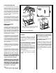
INSTALLATION INSTRUCTIONS MPB B-Vent Gas Fireplaces MODELS P/N 850033M Rev. G 01/2011 This manual is one of a set of two supporting this product. Refer to P/N 875031M for Care and Operation Instructions. Ce manuel est disponible en francais, simplement en faire la demande. Numéro de la pièce 850033CF.
PACKAGING LIST TABLE OF CONTENTS Packaging..........................................Page Introduction.......................................Page General Information...........................Page Massachusetts and New York Requirements.................................Page Cold Climate Insulation......................Page Manufactured Home Requirements...Page Location.............................................Page Vent Termination Clearances . ...........Page Appliance and Vent Clearances.........
WARNING Improper installation, adjustment, alteration, service or maintenance can cause injury or property damage. Refer to this manual. For assistance or additional information consult a qualified installer, service agency or the gas supplier. WARNING Failure to comply with these installation instructions will result in an improperly installed and operating appliance, voiding its warranty. Any change to this appliance and/or its operating controls is dangerous.
28,000 mpb4540 31,000 29,000 Table 2 Gas Pressure - All Models Tables 3 and 4 show the appliances' inlet and manifold gas pressure requirements: Maximum Natural Gas 5.0" WC (1.24 kPa) 10.5" WC (2.61 kPa) Propane 11.0" WC (2.74 kPa) 13.0" WC (3.23 kPa) Table 3 Manifold Gas Supply Pressure (all models) Fuel # Low High Natural Gas (Lo) 2.2" WC (0.55 kPa) (Hi) 3.5" WC (0.87 kPa) Propane (Lo) 6.3" WC (1.57 kPa) (Hi) 10.0" WC (2.
Cold Climate Insulation For cold climate installations, seal all cracks around your appliance with noncombustible material and wherever cold air could enter the room. It is especially important to insulate outside chase cavity between studs and under floor on which appliance rests, if floor is above ground level. Gas line holes and other openings should be caulked or stuffed with unfaced fiberglass insulation.
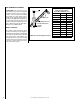
Vent Termination Clearances Termination Heights For Vents Above Flat Or Sloped Roofs Ref. NFPA 54 / ANSI Z223.1, 7.6 Gas Vent Rule - Gas vent caps are not per- mitted within 8 feet (2.4 mm) of a vertical wall or similar obstruction.
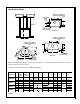
MINIMUM CLEARANCES TO COMBUSTIBLES MANTEL CLEARANCES Inches (mm) Appliance And Vent Clearances Maintain clearances from appliance to combustible materials as detailed in Table 6 with the following exception: When the unit is installed with one side flush with a wall, the wall on the other side of the unit must not extend beyond the front edge of the unit. In addition, when the unit is recessed, the side walls surrounding the unit must not extend beyond the front edge of the unit (see Figure 3).
WARNING Failure to position the parts in accordance with these diagrams or failure to use only parts specifically approved with this appliance may result in property damage or personal injury. AVERTISSEMENT Risque de dommages ou de blessures si les pièces ne sont pas installées conformément à ces schémas et ou si des pièces autres que celles spécifiquement approuvées avec cet appareil sont utilisées.
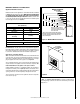
Framing specifications Back Wall of Chase/Enclosure Including Finishing Materials if any C *Optional FOAK Outside Air Kit G J Header A Rough Framing Face (Unfinished Shown) Outside Chase b A Fireplace Framing back Wall of Chase/Enclosure Including Finishing materials if any C back Wall of Chase/Enclosure Including Finishing materials if any G K d F A H G H C A E Corner Installation Inside Chase Rough Framing Face (Unfinished Shown) Rough Framing Face (Unfinished Shown) Note: All framing
fireplace specifications FRAMING SPACERS (Top and Sides and Rear) F G Flue Outlet For B-Vent Connection H J NOTE - Hood shown as positioned in louvered front model.
Step 2. ROUTE GAS SUPPLY LINE Route a 1/2" (13 mm) gas line as shown in Figure 11. Gas lines must be routed, constructed and made of materials that are in strict accordance with local codes and regulations. The appliance, as set up at the factory, is best suited for use with a gas line routed from the right side. The gas line may however be alternately routed from the left side. All appliances are factory-equipped with a flexible gas line connector and 1/2 inch shutoff valve. (See Step 6 on Page 14).
Step 3. INSTALL THE VENT SYSTEM & EXTERIOR TERMINATION: General Information These instructions should be used as a guideline and do not supersede local codes in any way. Install venting according to local codes, these instructions, the current National Fuel Gas Code (ANSI-Z223.1) in the USA or the current standards of CAN/CSA-B149.1 in Canada. 10 ft. 10 ft.minimum minimum Ensure clearances are in accordance with local installation codes and the requirements of the gas supplier.
CAUTION Ground supply lead must be connected to the wire attached to the green ground screw located on the outlet box. See Figures 17 or 18. Failure to do so will result in a potential safety hazard. The appliance must be electrically grounded in accordance with local codes or, in the absence of local codes, the National Electrical Code, ANSI/ NFPA 70-latest edition. (In Canada, the current CSA C22-1 Canadian Electrical Code). CAUTION: Label all wires prior to disconnection when servicing controls.
1. If any of the original wire as supplied must be replaced, 1. it must be replaced with Type AWM 105°C – 18 GA. wire. 2. 120V, 60Hz – Less than 3 amps. **Leave the ON/OFF switch, which is integral with the gas valve, in the ON position.
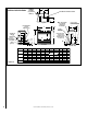
Gas Flex Line Connector 3/8" NPT x 1/2" x 3/8" Flare Flare Fitting Shut-off Valve Gas Valve 3/8" Flex Tubing 1/2" x 3/8" Reducer 3/8" Nipple 3/8" Union 3/8" Close Nipple 3/8" Shut-off Valve Gas Solid Line Connector Gas Stub Note: The gas supply line must be installed in accordance with building codes by a qualified installer approved and/or licensed as required by the locality. In the Commonwealth of Massachusetts, installation must be performed by a licensed plumber or gas fitter.
SIT Millivolt Appliance Checkout The pilot flame should be steady, not lifting or floating. Flame should be blue in color with traces of orange at the outer edge. (ref. Form # 750,008M) Outside Combustion Air Kits Cat. No. Model No.
Proper twig placement is critical to prevent sooting. Twigs should be placed in the gaps between the flame peaks and should be positioned so that at no time they impinge the flames. Glowing Embers 1. Remove the appliance front door. 2. Remove the log set from the interior of the fireplace. 3. Remove the logs from their packaging. Handle logs carefully to prevent breakage. 4. MPB-4035 & MPB-4540 Models - Remove the restraining strap from the grate tines.
MPB-3328 Log Placement LOG SET Catalog Number 24M1501 1 * Item 3 2 Description (stamped #) 1 Log, Rear (39-12) 2 Log, Left (39-1) 3 Log, Right (39-2) 4 Log, Top Center (39-13) 5 Log, Top/Left (39-3) 6 Log, Top/Right (39-4) * Item numbers above correspond to photos 4 5 1 6 Position the individual logs as shown below. Logs should be placed in the order shown. Position the rear log on the brackets at the rear of the firebox with the log's notches directly over the brackets.
MPB-3530 Log Placement LOG SET Catalog Number 24M2201 1 * Item 3 2 Description (stamped #) 1 Log, Rear (39-5) 2 Log, Left (39-1) 3 Log, Right (39-2) 4 Log, Top Center (39-6) 5 Log, Top/Left (39-3) 6 Log, Top/Right (39-4) * Item numbers above correspond to photos 4 6 5 1 Position the individual logs as shown below. Logs should be placed in the order shown. Position the rear log on the brackets at the rear of the firebox with the log's notches directly over the brackets.
MPB-4035 & MPB-4540 Log Placement LOG SET Catalog Number 24M2501 1 * Item 2 3 Description (stamped #) 1 Log, Center (39-8) 2 Log, Rear (138) 3 Log, Right (39-10) 4 Log, Left (39-9) 5 Log, Top/Left (39-11) 6 Log, Top/Right (39-11) * Item numbers above correspond to photos 4 5 Position the individual logs as shown below. Logs should be placed in the order shown. Position the center log on the burner first, then place the glowing embers as shown in Figure 28.
Step 10. INSTALLATION AND REMOVAL OF GLASS DOOR WARNING • Do not attempt to substitute the materials used on this door, or replace cracked or broken glass. • Handle this glass with extreme care! Glass is susceptible to damage – Do not scratch or handle roughly while reinstalling the glass door frame. • The glass door(s) of this appliance must only be replaced as a complete unit as provided by the manufacturer. Do not attempt to replace broken, cracked or chipped glass separately.
Step 11. Burner Adjustments Burner Air Shutter Adjustment Flame Appearance and Sooting Proper flame appearance is a flame which is blue at the base and becomes yellowish-orange in the body of the flame. When the appliance is first lit, the entire flame may be blue and will gradually turn yellowishorange during the first 15 minutes of operation.
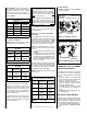
Step 12. Vent Operation Test Figure 34 Burner Flame Appearance - Model MPB-3328 After appliance installation, perform this vent operation test to verify that proper venting conditions exist: 1 - Place unit in its normally-operated condition, that is, with the glass enclosure panel in place. 2 - Close all doors and windows in the room. Turn on all exhaust fans in the house. 3 - Light the appliance. 4 - Wait 15 minutes.
4 - Remove the safety switch bracket securing screws (2), and pull the switch/bracket assembly, with low voltage wires attached, through the side panel slot into the firebox. See Figure 37, Detail C. 5 - Replace the switch. 6 - Reinstall the switch/bracket assembly. 7 - Reinstall the scoop and lintel. 8 - Reinstall the glass enclosure panel. 9 - Raise the bottom control compartment access panel. 10 - The appliance should then relight and remain lit.
Step 14. ATTACHING SAFETY IN OPERATION WARNINGS It is the installer's responsibility to ensure these warnings are properly affixed during installation. These warning labels are a critical step in informing consumers of safe operation of this appliance.
GAS CONVERSION KITS Electronic HONEYWELL Systems Natural Gas To Propane Gas Conversion Kits WARNING This conversion kit shall be installed by a qualified service agency in accordance with the manufacturer’s instructions and all applicable codes and requirements of the authority having jurisdiction. If the information in these instruction is not followed exactly, a fire, explosion or production of carbon monoxide may result causing property damage, personal injury or loss of life.
See Figure 42 and replace the pilot orifice as follows: Remove the igniter assembly retainer clip, and carefully remove the igniter assembly. SIT Millivolt Gas Valve Pressure Regulator Remove These Components Figure 39 b. Refer to Figure 40 and remove the pilot hood assembly to access the hexed pilot orifice. Remove and replace the orifice with the one provided with the kit. Exercise extreme care to prevent damage to or breakage of the igniter assembly.
Lennox Hearth Products reserves the right to make changes at any time, without notice, in design, materials, specifications, prices and also to discontinue colors, styles and products. Consult your local distributor for fireplace code information. Printed in U.S.A. © 2005 Lennox Hearth Products P/N 850033M Rev.