
Indoor Fireplace User Manual

4
NOTE: DIAGRAMS & ILLUSTRATIONS ARE NOT TO SCALE.
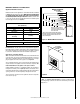
Manifold Gas Supply Pressure
(all models)
Fuel # Low
(millivolt only)
High
Natural
Gas
(Lo) 2.2" WC
(0.55 kPa)
(Hi) 3.5" WC
(0.87 kPa)
Propane
(Lo) 6.3" WC
(1.57 kPa)
(Hi) 10.0" WC
(2.49 kPa)
Table 4
Inlet Gas Supply Pressure
(all models)
Fuel # Minimum Maximum
Natural Gas
5.0" WC
(1.24 kPa)
10.5" WC
(2.61 kPa)
Propane
11.0" WC
(2.74 kPa)
13.0" WC
(3.23 kPa)
Table 3
Gas Pressure - All Models
Tables 3 and 4 show the appliances' inlet and
manifold gas pressure requirements:
REQUIREMENTS FOR THE COMMON-
WEALTH OF MASSACHUSETTS
Installation of these fireplaces are approved
for installation in the US state of Massachu-
setts if the following additional requirements
are met:
• Install this appliance in accordance with
Massachusetts Rules and Regulations 248
C.M.R. Sec. 5.08 2(a) through 2(e).
• Installation and repair must be doneby a
plumber or gas fitter licensed in the Com-
monwealth of Massachusetts.
• The exible gaslineconnectorusedshall
not exceed 36 inches (92 centimeters) in
length.
• The individualmanualshut-off mustbea
T-handle type valve.
NEW YORK CITY, NEW YORK (MEA)
Installation of these fireplaces are approved for
installation in New York City in the US state of
New York (approval no. MEA 417-05-E), if the
following additional requirements are met -
• Anoutsideairkit(FOAK-4orFOAK-4LD)
must be installed. See Figure 22 on Page
16.
Orifice Sizes - Sea Level to High Altitude
(All Models)
These appliances are tested and approved for
installation at elevations of 0-4500 feet (0-1372
meters) above sea level using the standard
burner orifice sizes (marked with an "*" in Table
5). For elevations above 4500 feet, contact your
gas supplier or qualified service technician.
Deration - At higher elevations, the amount
of BTU fuel value delivered must be reduced
by either:
• Usinggasthathasbeenderatedbythegas
company.
• Changingtheburneroricetoasmallersize
as regulated by the local authorities having
jurisdiction and by the (USA) National Fuel
Gas Code NFPA 54/ANSI Z223.1 - latest
edition or, in Canada, the CAN/CSA-B149.1
codes - latest edition.
Install the appliance according to the regulations
of the local authorities having jurisdiction and,
in the USA, the National Fuel Gas Code NFPA
54 / ANSI Z223.1 - latest edition or, in Canada,
the CAN/CSA-B149.1 - latest edition.
NOTE: Flame appearance will diminish 4% per
thousand feet.
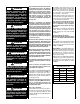
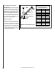
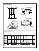
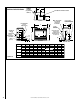
Gas Valve Diagrams
See Figure 1 for Millivolt models and Figure 2
For Electronic Models.
H
I
L
O
W
HTPTHTPT
P
I
L
O
T
P
I
L
O
T
O
N
it
O
F
F
IN
OUT
Manifold Pressure Tap
Inlet Pressure Tap
Pilot Adjustment
Screw
HI/LO Variable
Flame Height
Adjustment
Main Gas
Control Knob
OFF/PILOT/ON
Figure 1 - SIT Millivolt Gas Valve
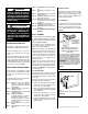
Figure 2 - Honeywell Electronic Gas Valve
FFO
NI
P
S
I
NO
LORTNOC
GI N TI ER
Manifold Pressure
Port
ON / OFF Switch
Inlet
Pressure
Port
Electronic Gas
Control Valve
Test gauge connections are provided on
the front of the millivolt gas control valve,
identified IN for the inlet and OUT for the
manifold side. A 1/8" NPT Test gauge connec-
tion is provided at the inlet and outlet side of
the electronic gas control valve adjacent to the
outlet to the main burner.
Propane tanks are at pressures that will cause
damage to valve components. Verify that the
tanks have step down regulators to reduce the
pressure to safe levels.
These appliances must be isolated from the
gas supply piping system (by closing their
individual manual shut-off valve) during any
pressure testing of the gas supply piping
system at test pressures equal to or less
than 1/2 psig (3.5 kPa).
These appliances and their individual shut-off
valves must be disconnected from the gas
supply piping system during any pressure
testing of that system at pressures greater
than 1/2 psig (3.5 kPa).
These appliances must not be connected to a
chimney or flue serving a separate solid fuel
burning appliance.
Electronic Models with
Fixed-Rate Gas Valve
Natural Gas Propane Gas
Model Input Rate
(BTU/HR)
Input Rate
(BTU/HR)
MPB3328
17,500 17,500
MPB3530
20,000 20,000
MPB4035
30,000 28,000
MPB4540
31,000 29,000
Table 2
Electronic Models - These electronic appliances
have a fixed rate gas valve and an electronic
intermittent pilot ignition system. External
electrical power is required to operate these
units. The BTU Input for these appliances is
shown in Table 2.
Burner Orifice Sizes
Elevation 0-4500 feet ( 0-1372 meters)
Model
Series
Nat.Gas
drill size (inches)
Propane
drill size (inches)
MPB-3328 #47 (.0785") *
39L66 •
#1.2m (.048")*
99K78 •
MPB-3530 #44 (.086") *
60J80 •
#55 (.052") *
19L52 •
MPB-4035 #37 (.104") *
24M10 •
1/16"
(.0625") *
21L01 •
MPB-4540 #36 (.1065") *
18L40 •
#52
(.0635") *
37G00 •
Table 5
* Standard size installed at factory
• Part /Cat. Number