
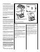
Indoor Fireplace User Manual

8
NOTE: DIAGRAMS & ILLUSTRATIONS ARE NOT TO SCALE.
Step 7. (Page 15) Outside Air Kit Installa-
tion.
Step 8. (Page 16) Verify appliance opera-
tion.
Step 9. (Page 16) Install grate, vermiculite,
embers and logs.
Step 10. (Page 21) Installation/Removal of
glass enclosure panels.
Step 11. (Page 22) Adjust burner primary
air shutter to achieve proper flame
appearance.
Step 12. (Page 23) Vent operation test and
(safety limit) switch operation.
Step 13. (Page 24) Install the decorative trims
and hoods.
Step 14. (Page 25) Attach Safety in Operation
Warnings.
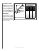
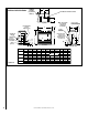
Step 1. FRAMING
Frame these appliances as illustrated in Figure
9. All framing details must allow for a minimum
clearance to combustible framing members as
shown in Table 6 on Page 7.
If the appliance is to be elevated above floor
level, a solid continuous platform must be
constructed below the appliance.
Note: The framed depth, 16 in. (406 mm) from
a framed wall, must always be measured from
a finished surface. If a wall covering such as
drywall is to be attached to the rear wall, then
the 16 in. (406 mm) must be measured from
the drywall surface. It is important that this
dimension be exact.
Headers may be in direct contact with the
appliance top spacers but must not be sup-
ported by them or notched to fit around them.
All construction above the appliance must be
self-supporting, DO NOT use the appliance for
structural support.
Pre-installation Notes
The fireplace may be positioned and then the
framing built around it, or the framing may be
constructed and the fireplace positioned into
the opening.
Usually, no special floor support is needed for
the fireplace, however, to be certain:
1. Estimate the total weight of the fireplace
system and surround materials such as
brick, stone, etc., to be installed.
2. Measure the square footage of the floor space
to be occupied by the system, surrounds and
hearth extensions.
3. Note the floor construction, i.e. 2 x 6’s, 2 x
8’s or 2 x 10’s, single or double joists, type
and thickness of floor boards.
4. Use this information and consult your local
building code to determine if you need ad-
ditional support.
DETAILED INSTALLATION STEPS
The appliance is shipped with all gas controls
and components installed and pre-wired.
1. Remove the shipping carton. Remove the
shipping pad, exposing the front glass
door.
2. Open the two latches (located under the fire-
box floor) securing the glass door. Remove
the door by tilting it outward at the bottom
and lifting it up. Set the door aside protecting
it from inadvertent damage. See Removing
Glass Enclosure Panel on Page 21.
TYPICAL INSTALLATION SEQUENCE
The typical sequence of installation is outlined
below. However, each installation is unique
and may result in variations to the steps
described.
See the Page numbers references in the follow-
ing steps for detailed procedures.
Step 1. (Page 8) - Construct the appliance
framing. Position the appliance
within the framing and secure with
nailing flanges.
Step 2. (Page 11) Route gas supply line to
appliance location.
Step 3. ( Page 12) Install the vent system and
exterior termination.
Step 4. (Page 13) Field Wiring
a. Millivolt Appliances – Install the
OFF/ON burner control switch.
b. Electronic Appliances – Connect
120 VAC electrical power to the appli-
ance receptacle.
Step 5. (Page 14) Install the optional
blower.
Step 6. (Page 14) Make connection to gas
supply.
WARNING
Failure to position the parts in
accordance with these diagrams
or failure to use only parts specifi-
cally approved with this appliance
may result in property damage or
personal injury.
AVERTISSEMENT
Risque de dommages ou de
blessures si les pièces ne sont
pas installées conformément à
ces schémas et ou si des pièces
autres que celles spécifiquement
approuvées avec cet appareil sont
utilisées.
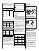
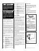
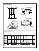
Figure 8
Figure 7
Note:
Some units only have one anchor tab on each side.
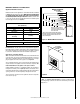
Note: The nailing flanges, combustible members
and screw heads located in areas directly adjacent
to the nailing flanges, are EXEMPT from the 1/2”
clearance to combustible requirements for the
firebox outer wrapper. Combustible framing may be
in direct contact with the nailing flanges and may
be located closer than 1/2” from screw heads and
the firebox wrapper in areas adjacent to the nailing
flanges. Frame the opening to the exact dimensions
specified in the framing details of this manual.
Side
Framing
Unit Nailing Flange
(No clearance to
combustible
framing is required)
Left Side Front Corner of Fireplace Shown
(Right Side Requirements the Same)
Unit Being Secured By Its Nailing Flanges
To The Framing
Anchor
Ta b
Side Nailing Flanges
The fireplace should be secured to the side
framing members using the unit's nailing
flanges - two at the top and bottom on each
side of the fireplace front. See Figure 7. Use
8d nails or their equivalent.
Floor Nailing Tabs
Fireplace may be anchored to floor. Bend down
two anchor tabs (one on each side) located
at the base of the fireplace and secure to the
floor by nailing with 8d nails or equivalent
(Figure 8).