Lenovo C260 All-In-One PC Hardware Maintenance Manual ideaideaideaCentreidea Machine Types: 10160/F0AK [C260]
Lenovo C260 All-In-One PC Hardware Maintenance Manual Machine Types: 10160/F0AK [C260]
First Edition (February 2014)25th © Copyright Lenovo 2013, 2014. LIMITED AND RESTRICTED RIGHTS NOTICE: If data or software are delivered pursuant a General Services Administration “GSA” contract, use, reproduction, or disclosure is subject to restrictions set forth in Contract No.
Contents Chapter 1. About this manual . . . . . . 1 Important Safety Information . . . . . . . . . . 1 Chapter 2. Safety information . . . . . . 3 General safety . . . . . . . . . . . . Electrical safety . . . . . . . . . . . Safety inspection guide . . . . . . . . Handling electrostatic discharge-sensitive devices . . . . . . . . . . . . . . Grounding requirements . . . . . . . . Safety notices . . . . . . . . . . . . . . . . . . . . . . . . 3 3 5 . . . . . . . . . . . . 5 6 6 Chapter 3.
iv Lenovo C260 All-In-One PC Hardware Maintenance Manual
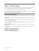
Chapter 1. About this manual This manual contains service and reference information for Lenovo C260 All-In-One computer listed on the cover. It is intended only for trained servicers who are familiar with Lenovo computer products. Before servicing a Lenovo product, be sure to read the Safety Information. The description of the TV-tuner card in this manual applies only to computers with a TV-tuner card installed. It does not apply to computers without a TV-tuner card.
2 Lenovo C260 All-In-One PC Hardware Maintenance Manual
Chapter 2. Safety information This chapter contains the safety information that you need to be familiar with before servicing a computer. General safety Follow these rules to ensure general safety: • Keep the areas around the computer clear and clean during and after maintenance. • When lifting any heavy object: 1. Ensure you can stand safely without slipping. 2. Distribute the weight of the object equally across both feet. 3. Lift slowly. Never move suddenly or twist when you attempt to lift. 4.
Observe the following rules when working on electrical equipment. Important: Use only approved tools and test equipment. Some hand tools have handles covered with a soft material that does not insulate you when working with live electrical currents. Many customers have rubber floor mats near their equipment that contain small conductive fibers to decrease electrostatic discharge. • Find the room emergency power-off (EPO) switch, disconnecting switch, or electrical outlet.
– Switch off power. – Send another person to get medical aid. Safety inspection guide The intent of this inspection guide is to assist you in identifying potential hazards posed by these products. Each computer, as it was designed and built, had required safety items installed to protect users and service personnel from injury. This guide addresses only those items.
• Keep the parts in protective packages until they are inserted into the product. • Avoid contact with other people while handling the part. • Wear a grounded wrist strap against your skin to eliminate static on your body. • Prevent the part from touching your clothing. Most clothing is insulative and retains a charge even when you are wearing a wrist strap. • Use the black side of a grounded work mat to provide a static-free work surface. The mat is especially useful when handling ESD-sensitive devices.
To Connect To Disconnect 1. Turn everything OFF. 1. Turn everything OFF. 2. First, attach all cables to devices. 2. First, remove power cords from outlets. 3. Attach signal cables to connectors. 3. Remove signal cables from connectors. 4. Attach power cords to outlet. 4. Remove all cables from devices. 5. Turn device ON. CAUTION: When replacing the lithium battery, use only Part Number 45C1566 or an equivalent type battery recommended by the manufacturer.
≥18 kg (37 lbs) ≥32 kg (70.5 lbs) ≥55 kg (121.2 lbs) CAUTION: Use safe practices when lifting. CAUTION: The power control button on the device and the power switch on the power supply do not turn off the electrical current supplied to the device. The device also might have more than one power cord. To remove all electrical current from the device, ensure that all power cords are disconnected from the power source. 2 1 CAUTION: Do not place any object weighing more than 82 kg (180 lbs.
Chapter 3. General information This chapter provides general information that applies to all computer models covered by this manual. Specifications This section lists the physical specifications for your computer. This section lists the physical specifications for your computer. Type Lenovo C260 This section lists the physical specifications.
10 Lenovo C260 All-In-One PC Hardware Maintenance Manual
Chapter 4. General Checkout Attention: The drives in the computer you are servicing might have been rearranged or the drive startup sequence may have been changed. Be extremely careful during write operations such as copying, saving, or formatting. Data or programs can be overwritten if you select an incorrect drive. General error messages appear if a problem or conflict is found by an application, the operating system, or both.
12 Lenovo C260 All-In-One PC Hardware Maintenance Manual
Chapter 5. Using the Setup Utility The Setup Utility program is used to view and change the configuration settings of your computer, regardless of which operating system you are using. However, the operating system settings might override any similar settings in the Setup Utility program. Starting the Lenovo BIOS Setup Utility program To start the Lenovo BIOS Setup Utility program, do the following: 1.
Administrator Password Setting an Administrator Password deters unauthorized persons from changing configuration settings. You might want to set an Administrator Password if you are responsible for maintaining the settings of several computers. After you set an Administrator Password, a password prompt is displayed every time you access the Lenovo BIOS Setup Utility program. If both the Administrator and Power-On Password are set, you can type either password.
Power-On Password When a Power-On Password is set, you cannot start the Lenovo BIOS Setup Utility program until a valid password is typed from the keyboard. Setting, changing, or deleting a Power-On Password Note: A password can be any combination of letters and numbers up to 16 characters (a-z and 0-9). To set a Power-On Password, do the following: 1. Start the Lenovo BIOS Setup Utility program (see ”Starting the Lenovo BIOS Setup Utility program” on page 13). 2.
SATA Mode Select Disabled/IDE/AHCI mode. Device driver support is required for AHCI or RAID. Depending on how the hard disk drive image was installed, changing this setting may prevent the system from booting. Onboard Audio Controller Select whether to enable or disable the Onboard Audio Controller. When this feature is set to Disabled all devices connected to the audio connectors (e.g. headphones or a microphone) are disabled and cannot be used.
Selecting or changing the startup device sequence To view or permanently change the configured startup device sequence, do the following: 1. Start the Lenovo BIOS Setup Utility program (see “Starting the Lenovo BIOS Setup Utility program” on page 13). 2. From the Lenovo BIOS Setup Utility program main menu, select the Startup option. 3. Press the Enter key, and select the devices for the Primary Boot Sequence. Read the information displayed on the right side of the screen. 4.
18 Lenovo C260 All-In-One PC Hardware Maintenance Manual
Chapter 6. Symptom-to-FRU Index The Symptom-to-FRU index lists error symptoms and possible causes. The most likely cause is listed first. Always begin with Chapter 4, “General Checkout,” on page 11. This index can also be used to help you decide which FRUs to have available when servicing a computer. If you are unable to correct the problem using this index, go to “Undetermined problems” on page 20. Notes: • If you have both an error message and an incorrect audio response, diagnose the error message first.
POST error codes Each time you turn the computer on, it performs a series of tests to check that the system is operating correctly and that certain options are set. This series of tests is called the Power-On Self-Test, or POST. POST does the following: • Checks some basic motherboard operations • Checks that the memory is working correctly • Starts video operations • Verifies that the boot drive is working POST Error Message Description/Action Keyboard error Cannot initialize the keyboard.
Chapter 7. Replacing hardware Attention: Do not remove the computer cover or attempt any repair before reading the “Important safety information” in the Safety and Warranty Guide that was included with your computer. To obtain copies of the Safety and Warranty Guide, go to the Support Web site at: http://support.lenovo.com. Note: Use only parts provided by Lenovo. General information Pre-disassembly instructions Before starting the disassembly procedure, make sure that you do the following: 1.
Replacing the keyboard and mouse To replace the keyboard and mouse: Step 1. Remove any media (disks, CDs, DVDs or memory cards) from the drives, shut down the operating system, and turn off the computer and all attached devices. Step 2. Unplug all power cords from electrical outlets. Step 3. Disconnect all cables attached to the computer. This includes power cords, input/output (I/O) cables, and any other cables that are connected to the computer.
Step 3. Disconnect the failing power adapter from the computer. Step 4. To install the new power adapter: a. Connect the new power adapter to the same connector. Chapter 7.
Replacing the computer stand Note: Turn off the computer and wait 3 to 5 minutes to let it cool down before removing the rear cover. To replace the computer stand: Step 1. Remove any media (disks, CDs, DVDs, or memory cards) from the drives, shut down the operating system, and turn off the computer and all attached devices. Step 2. Unplug all power cords from electrical outlets. Step 3. Disconnect all cables attached to the computer.
Step 5. Remove the 2 screws that secure the computer stand to the rear cover. Step 6. Slide out the computer stand as shown. Step 7. To install the new computer stand: a. Line up the computer stand with the mounting hole on the rear cover and slide it into position. b. Secure the new computer stand to the rear cover with the 2 screws. c. Reattach the stand cover. Removing the rear cover Note: Turn off the computer and wait 3 to 5 minutes to let it cool down before removing the rear cover.
Note: It may be helpful to place the computer face-down on a soft flat surface for this procedure. Lenovo recommends that you use a blanket, towel, or other soft cloth to protect the touch screen from scratches or other damage. To remove the rear cover: Step 1. Remove any media (disks, CDs, DVDs, or memory cards) from the drives, shut down the operating system, and turn off the computer and all attached devices. Step 2. Unplug all power cords from electrical outlets. Step 3.
Step 5. Lift up the rubbers that protect the 2 screws, remove the 2 screws that secure the rear cover to the front bezel. Step 6. The rear cover and front bezel are pinned together, use a plastic flat-head screwdriver, insert to the gap in-between the rear cover and the front bezel, slide the screwdriver along the bottom edge to loose it, then lift up the rear cover as shown. Chapter 7.
Step 7. Disconnect the LVDS cable to separate the rear cover from the front bezel. Step 8. To reattach the rear cover: a. Line up the rear cover with the front bezel and reconnect the LVDS cable. b. Line up the holes on the rear cover with mounting holes on the front bezel, and place the rear cover into position. c. Secure the rear cover to the front bezel with the 2 screws. d. Reattach the stand and the cover.
Step 5. Slide out the optical drive as shown. Step 6. Use a small flat head screwdriver to press and push out the pins that secure the cover to the disk. 4 5 Step 7. Separate the cover from the defective optical drive. Step 8. Install the new optical drive as follows: a. Align the new optical drive with the cover, and then push the cover back into position. b. Slide the new optical drive into the drive bay, then push it into position. c.
Replacing a memory module Attention: Turn off the computer and wait 3 to 5 minutes to let it cool down before removing the rear cover. To replace a memory module: Step 1. Remove any media (disks, CDs, DVDs, or memory cards) from the drives, shut down the operating system, and turn off the computer and all attached devices. Step 2. Unplug all power cords from electrical outlets. Step 3. Disconnect all cables attached to the computer.
Step 3. Disconnect all cables attached to the computer. This includes power cords, input/output (I/O) cables, and any other cables that are connected to the computer. Refer to “Left and right view” and “Rear view” for help with locating the various connectors. Step 4. Remove the rear cover. Refer to "Removing the rear cover". Step 5. Remove the 6 screws that secure the hard disk drive to the rear cover. Step 6. Disconnect the data and power cable from the hard disk drive. Step 7.
d. Connect the data and power cables to the new hard disk drive. Step 10. Reattach the rear cover, stand and stand cover. Replacing the Wi-Fi card Note: Turn off the computer and wait 3 to 5 minutes to let it cool down before removing the rear cover. To replace the Wi-Fi card: Step 1. Remove any media (disks, CDs, DVDs, or memory cards) from the drives, shut down the operating system, and turn off the computer and all attached devices. Step 2. Unplug all power cords from electrical outlets. Step 3.
Step 1. Remove any media (disks, CDs, DVDs, or memory cards) from the drives, shut down the operating system, and turn off the computer and all attached devices. Step 2. Unplug all power cords from electrical outlets. Step 3. Disconnect all cables attached to the computer. This includes power cords, input/output (I/O) cables, and any other cables that are connected to the computer. Refer to “Left and right view” and “Rear view” for help with locating the various connectors. Step 4.
Step 3. Disconnect all cables attached to the computer. This includes power cords, input/output (I/O) cables, and any other cables that are connected to the computer. Refer to “Left and right view” and “Rear view” for help with locating the various connectors. Step 4. Remove the rear cover. Refer to "Removing the rear cover". Step 5. Remove the screw that secures the power switch board to the rear cover and lift up the power switch board to remove it. 2 Step 6.
Step 5. Disconnect the power cable from the connector on the motherboard. Step 6. Remove the 2 screws that secure the system fan to the rear cover. Step 7. Lift up the system fan to remove it. Step 8. To install the new system fan: Step 9. a. Line up the new system fan with the mounting holes on the rear cover and place it into position. b. Secure the new system fan to the rear cover with the 2 screws. c. Connect the new power cable to the connector on the motherboard.
Step 8. Remove all the cables connected to the motherboard. Step 9. Remove the 8 screws that secure the motherboard to the rear cover and lift it up to remove it. Step 10. Remove the heat-sink as shown. Step 11. To install the new motherboard: a. Attach the heat-sink, Wi-Fi card, memory modules to the new motherboard. b. Line up the holes on the new motherboard with the mounting holes on the rear cover and secure the new motherboard with the 8 screws. c.
Replacing the heat-sink Note: Turn off the computer and wait 3 to 5 minutes to let it cool down before removing the rear cover. To replace the heat-sink: Step 1. Remove any media (disks, CDs, DVDs or memory cards) from the drives, shut down the operating system, and turn off the computer and all attached devices. Step 2. Unplug all power cords from electrical outlets. Step 3. Disconnect all cables attached to the computer.
Replacing the camera Note: Turn off the computer and wait 3 to 5 minutes to let it cool down before removing the rear cover. To replace the camera: Step 1. Remove any media (disks, CDs, DVDs, or memory cards) from the drives, shut down the operating system, and turn off the computer and all attached devices. Step 2. Unplug all power cords from electrical outlets. Step 3. Disconnect all cables attached to the computer.
Step 5. Remove the 2 screws that secure the camera to the front bezel. Step 6. Gently slide out the camera and disconnect the cable from the camera. Step 7. To install the new camera: Step 8. a. Connect the data cable to the new camera. b. Line up the holes in the new camera with the mounting holes on the front bezel and secure the new camera with the 2 screws. Reattach the rear cover, stand and stand cover.
Step 1. Remove any media (disks, CDs, DVDs, or memory cards) from the drives, shut down the operating system, and turn off the computer and all attached devices. Step 2. Unplug all power cords from electrical outlets. Step 3. Disconnect all cables attached to the computer. This includes power cords, input/output (I/O) cables, and any other cables that are connected to the computer. Refer to “Left and right view” and “Rear view” for help with locating the various connectors. Step 4.
Step 9. a. Line up the holes in the new converter board with the mounting holes on the bracket and secure the new converter board with the screw. b. Connect the 2 cables to the new converter board. Reattach the rear cover and secure it with the screws. Replacing the LED panel Note: Turn off the computer and wait 3 to 5 minutes to let it cool down before removing the rear cover. To replace the LED panel: Step 1.
Step 7. 42 Disconnect the LVDS and converter cables from the connector on the LED panel.
Step 8. Remove the 7 screws that secure the LED panel to the front bezel. The LED panel is glued to the front bezel, gently remove the LED panel from the front bezel. Step 9. Remove the 4 screws that secure the LED panel to the bracket to separate the LED panel from the bracket. Step 10. To install the new the LED panel: a. Line up the new LED panel with bracket, and secure it to the bracket with 4 screws. b. Line up the new LED panel with the front bezel, then place it into position. c.
Step 11. Reattach the converter board, camera, rear cover, stand and stand cover.
Chapter 8. Additional Service Information This chapter provides additional information that the service representative might find helpful. Power management Power management reduces the power consumption of certain components of the computer such as the system power supply, processor, hard disk drives, and some monitors.