
Heat Pump User Manual


Page 7
XP14 SERIES
New Outdoor Unit Placement
CAUTION
In order to avoid injury, take proper precaution when lift-
ing heavy objects.
Remove existing outdoor unit prior to placement of new
outdoor unit. See Unit Dimensions on page 2 for sizing
mounting slab, platforms or supports. Refer to figure 5 for
mandatory installation clearance requirements.
POSITIONING CONSIDERATIONS
Consider the following when positioning the unit:
Some localities are adopting sound ordinances based
on the unit’s sound level registered from the adjacent
property, not from the installation property. Install the
unit as far as possible from the property line.
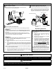
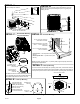
When possible, do not install the unit directly outside
a window. Glass has a very high level of sound
transmission. For proper placement of unit in relation
to a window see the provided illustration in figure 6,
detail A.
PLACING UNIT ON SLAB
When installing unit at grade level, the top of the slab
should be high enough above grade so that water from
higher ground will not collect around the unit. The slab
should have a slope tolerance as described in figure 6,
detail B.
NOTE If necessary for stability, anchor unit to slab as
described in figure 6, detail D.
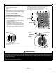
ELEVATING THE UNIT
Units are outfitted with elongated support feet as illustrated
in figure 6, detail C.
If additional elevation is necessary, raise the unit by
extending the height of the unit support feet. This may be
achieved by using a 2 inch (50.8mm) schedule 40 female
threaded adapter.
NOTE Keep the height of extenders short enough to
ensure a sturdy installation. If it is necessary to extend
further, consider a different type of field−fabricated
framework that is sturdy enough for greater heights.
ROOF MOUNTING
Install the unit a minimum of 6 inches (152 mm) above the
roof surface to avoid ice build−up around the unit. Locate
the unit above a load bearing wall or area of the roof that
can adequately support the unit. Consult local codes for
rooftop applications. See figure 6, detail F for other roof top
mounting considerations.
NOTICE
Roof Damage!
This system contains both refrigerant and oil. Some
rubber roofing material may absorb oil and cause the
rubber to swell when it comes into contact with oil. The
rubber will then bubble and could cause leaks. Protect
the roof surface to avoid exposure to refrigerant and oil
during service and installation. Failure to follow this
notice could result in damage to roof surface.
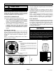
24
(610)
48 (1219)
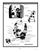
MINIMUM CLEARANCE BETWEEN TWO UNITS
CLEARANCE ON ALL SIDES INCHES (MILLIMETERS)
CONTROL PANEL ACCESS
LOCATION
MINIMUM CLEARANCE
ABOVE UNIT
NOTES:
Service clearance of 30 inches (762 mm) must be
maintained on one of the sides adjacent to the
control panel
Clearance to one of the other three sides must be 36
inches (914mm).
Clearance to one of the remaining two sides may be
12 inches (305mm) and the final side may be 6
inches (152mm).
Figure 5. Installation Clearances