LevelOne FSW-0507TX FSW-0807TX 5/8 Port 10/100M PalmCon Switch User’s Guide
FCC Warning This equipment has been tested and found to comply with the regulations for a Class B digital device, pursuant to Part 15 of the FCC Rules. These limits are designed to provide reasonable protection against harmful interference when the equipment is operated in a commercial environment. This equipment generates, uses, and can radiate radio frequency energy and, if not installed and used in accordance with this user’s guide, may cause harmful interference to radio communications.
TABLE OF C ONTENTS ABOUT THIS GUIDE................................................. 1 PURPOSE........................................................................................1 TERMS/USAGE ............................................................................1 OVERVIEW OF THIS USER’S GUIDE...................................1 INTRODUCTION ............................................................ 7 FEATURES ...................................................................................
SWITCH TO SWITCH (OTHER DEVICES ) ...........................10 PORT SPEED & DUPLEX M ODE.........................................11 TECHNICAL SPECIFICATIONS ...............
A BOUT T HIS G UIDE Congratulations on your purchase of the LeveOne 5/8 Port 10/100Mbps PalmCon Switch. This device integrates 100Mbps Fast Ethernet and 10Mbps Ethernet network capabilities in a highly flexible desktop package.
I NTRODUCTION This chapter describes the features of the Switch and some background information about Ethernet/Fast Features The Switch was designed for easy installation and high performance in an environment where traffic on the network and the number of user increase continuously. The Switch with its small, compact size was specifically designed for small to middle workgroups.
the transmit and receive nodes to guarantee against all possible packet loss. The Switch is a managed 10/100 Fast Ethernet Switch that offers solutions in accelerating small Ethernet workgroup bandwidth. Other key features are: Auto-MDI function supports automatic MDI/MDIX crossover detection function gives true ‘plug and play’ capability without the need of confusing crossover cables or crossover ports. Store and forward switching scheme capability.
U NPACKING AND S ETUP This chapter provides unpacking and setup information for the Switches. Unpacking Open the shipping cartons of the Switch and carefully unpacks its contents. The carton should contain the following items: One LevelOne 5/8 Port 10/100Mbps PalmCon Switch One external power adapter This User’s Guide If any item is found missing or damaged, please contact your local reseller for replacement.
1 2 10
3 11
12
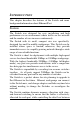
I DENTIFYING E XTERNAL C OMPONENTS This section identifies all the major external components of the hub. Both the front and rear panels are shown, followed by a description of each panel feature. The indicator panel is described in detail in the next chapter. Front Panel The figure below shows the front panels of the switch.
FSW-0507TX 1 2 3 4 5 6 7 8 7.5VDC/1A FSW-0807TX DC Power Jack: Power is supplied through an external AC power adapter. Check the technical specification section for information about the AC power input voltage. Since the switch does not include a power switch, plugging its power adapter into a power outlet will immediately power it on.
Full-Duplex/Collision (Full-Duplex/Collision) This LED indicator light green when a respective port is in full duplex (FDX) mode. Otherwise, it is blinking when collisions are occurring on the respective port. Link/Activity (100M=green, 10M=amber) This indicator light green when the port is connected to a 100Mbps Fast Ethernet station, if the indicator blinking green will be transmit or received data on the 100Mbps network.
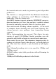
C ONNECTING T HE S WITCH This chapter describes how to connect the Switch to your Fast Ethernet network. In each of the following figures, the LevelOne 5/8 Port 10/100Mbps PalmCon Switch is shown. PC to Switch A PC can be connected to the Switch via a two-pair Category 3, 4, 5 UTP/STP cables. The PC (equipped with a RJ-45 10/100Mbps phone jack) should be connected to any of the 5/8 ports. The LED indicators for PC connection dependent on the LAN card capabilities.
Hub to Switch A hub (10 or 100BASE-TX) can be connected to the Switch via a two-pair Category 3, 4, 5 UTP/STP cable. The connection is accomplished from the hub to any of the Switch RJ-45 ports. A. 10BASE-T Hub For a 10BASE-T hub, the Switch LED indicators should light up as the following: “Full-Duplex/Collision” indicator is OFF. “100LINK/ACT, 10LINK/ACT LED” indicator is light amber. B.
Port Speed & Duplex Mode After plugging the selected cable to a specific port, the system uses auto-negotiation to determine the transmission mode for any new twisted-pair connection: If the attached device does not support auto-negotiation or has auto-negotiation disabled, an auto-sensing process is initiated to select the speed and set the duplex mode to halfduplex.
T ECHNICAL S PECIFICATIONS General Standards IEEE 802.3 10BASE -T Ethernet IEEE 802.3u 100BASE-TX Fast Ethernet ANSI/IEEE 802.3 NWay Auto-negotiation IEEE 802.3x Full duplex Flow Control Protocol CSMA/CD Data Transfer Rate Ethernet: 10Mbps Topology Star Network Cables 10BASE-T: 2-pair UTP Cat. 3,4,5, EIA/TIA- 568 STP Number of Ports (half duplex), 20Mbps (full-duplex) Fast Ethernet: 100Mbps (half duplex), 200Mbps (full- duple x) 100BASE-TX: 2-pair UTP Cat.
Physical and Environmental DC inputs 7.5VDC/1A Power Consumption 7.5 watts. (max.