LevelOne WAP-1001 11g Outdoor Wireless AP/Bridge User Manual Ver.1.
FCC Notice NOTE: This equipment has been tested and found to comply with the limits for a Class B digital device, pursuant to part 15 of the FCC Rules. These limits are designed to provide reasonable protection against harmful interference in a residential installation. This equipment generates, uses and can radiate radio frequency energy and, if not installed and used in accordance with the instructions, may cause harmful interference to radio communications.
The Wireless Technology Standard The Wireless Access Point utilizes the 802.11b and the 802.11g standards. The IEEE 802.11g standard is an extension of the 802.11b standard. It increases the data rate up to 54 Mbps (108Mbps in Super G mode) within the 2.4GHz band, utilizing OFDM technology. This means that in most environments, within the specified range of this device, you will be able to transfer large files quickly or even watch a movie in MPEG format you’re your network without noticeable delays.
Roaming Infrastructure mode also supports roaming capabilities for mobile users. Roaming means that you can move your wireless PC within your network and the access points will pick up the wireless PC's signal, providing that they both share the same channel and SSID. Before enabling you consider roaming, choose a feasible radio channel and optimum access point position. Proper access point positioning combined with a clear radio signal will greatly enhance performance.
z ceiling (instead of at an angle) for better reception. Building materials can impede the wireless signal - a solid metal door or aluminum studs may have a negative effect on range. Try to position wireless devices and computers with wireless adapters so that the signal passes through drywall or open doorways and not other materials.
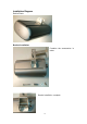
Installation Diagram Device Photo Bracket Installation Combine the accessories in order. Bracket installation complete.
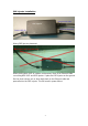
POE Injector Installation Connection instruction Wrong POE injector placement. When placing WAP-1001 in outdoor environment, there is an Ethernet cable connecting WAP-1001 and POE Injector. If place the POE injector on the ground like the photo shown, rain or dust might leak via the Ethernet cable and permeate into the POE injector. This will result in power failure.
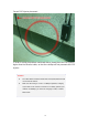
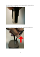
Correct POE injector placement In order to avoid the problem mentioned above, please place the POE injector higher than the Ethernet cable, so that the raindrop will not permeate the POE injector. Attention: z The cable distance between the Router and PC/hub/Switch should not exceed 100 meters. z Make sure the wiring is correct. In 10Mbps operation, Category 3/4/5 cable can be used for connection. To reliably operate your network at 100Mbps, you must use Category 5 cable, or better Data Grade.
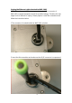
Unplug the Ethernet cable attached to WAP-1001 WAP-1001 conforms to IP66 water approval standard. The connector of WAP-1001 is special designed to avoid the possible leakage. Therefore the user might find it is difficult to unplug. Please prepare a small flat screwdriver and follow the instruction below: 1.The connector is located inside the WAP-1001 as below. 2.Insert the flat screwdriver and make sure that RJ45 connector is compressed.
3.At this moment, the screwdriver should compressed RJ45 connector like the picture below inside the WAP-1001. 4.Hold the screwdriver and the Ethernet cable, and pull out simultaneously.
AP Configuration Using Locator While entering the Locator utility, the Locator will automatically search the available WAP-1001 on the same network. Locator will show the Device Name, Device Type, IP Address, Ethernet MAC Address and Firmware Version in first page. Before start using Locator, make sure you disable personal firewall installed in you PC. (Ex.
2. 3. Enter the factory default User name and Password fields: User Name: Admin Password: (leave blank) then click OK button. You will enter the Utility homepage. Start Setup by Locator... 1. You just need to click on the “Web” icon in Locator main page.
Wireless Configuration - AP Mode System Status– The first page appears in main page will show “System Status -> System Summary” automatically, you can find detail system configuration in this page including z z z System Information – This will display system name and both Ethernet MAC address and Wireless MAC address. Current country setting and firmware version will also be available here.
The first page appears in main page will show “System Status -> Wireless Station List” automatically, this page can help user identify current devices who already associated to the AP. You can also click on the MAC address column then the system will show the detail technical information for each wireless station. Clicking MAC address hyperlink of desired remote devices, system will show a Statistics page for you to monitor the information of the remote link.
Field Description RSSI Displays the strength of the received signal in dBm (the remote devices received signal strength). Refresh every 2 seconds. RSSI of ACK Displays the strength of the ACK signal from far end in dBm (the local devices received signal strength). Refresh every 2 seconds. MSDU Maximum service data unit. Displays the number of packets sent and received by the remote devices. Data / Management Packets can be data, management or control.
The page below describes the detail connection information with each station. You can get all information needed right here. System Configuration – Now you can start to configure the system. In System Properties page, you can config z Device Name – You may assign any name to the Access Point. Memorable, Unique names are helpful especially if you are employing multiple access points on the same network. The device name needs to be less than 32 characters.
network architecture, In order to establish the wireless link between bridge radios, the MAC address of remotes bridge(s) need to be registered in the address table. Type the MAC address with format xx:xx:xx:xx:xx:xx (x is the hexadecimal digit) and use “Apply” and “Clear” button to edit the address table. A Master Bridge Radio may accommodate up to 8 remote MAC addresses. Administration – In the administration page, you can modify “Administrator Name” and “Password”.
IP Settings – IP Setting page can configure system IP address. Default IP address is 192.168.1.20 and Subnet Mask is 255.255.0.0. You can manually input IP address setting or get an IP from a DHCP server. z z z z IP Network Setting – Here you can choose to get IP from a DHCP server or specify IP address manually. Choose to obtain an IP address from DHCP server if your environment or ISP provide DHCP server. Otherwise, you can manually setup IP address.
Wireless Network At Wireless Network page can set “SSID” / “Wireless Mode” and “Channel”. AP supports not only standard 11b/g but also 108M SuperG. (Note: 108 M SuperG only works with Atheros® based 11a/g solution) z z z z Wireless Network Name (SSID) - The SSID is the unique name shared among all points in a wireless network. The SSID must be identical for all points in the wireless network. It is case-sensitive and must not exceed 32 alphanumeric characters, which may be any keyboard character.
z wireless network must use the same channel in order to function correctly. The default setting is “SmartSelect” means the system will pick best channel for you automatically. Stay with default setting if you do not have special request on channel selection. Stations Separation – Default setting is “Disable”. This option can disallow the client devices connected to this AP could not access each other. Wireless Security The wireless security settings configure the security of your wireless network.
WEP is a basic encryption method, which is not as secure as WPA. To use WEP, you will need to select a default transmit key and a level of WEP encryption, z z z Authentication type – Select “Open System” to communicate the key across the network. Select “Share Key” to limit communication to only those devices that share the same WEP settings.
WPA-PSK stands for Wi-Fi Protected Access – Pre-Shared Key. WPA-PSK is design for home users who do not have RADIUS server in their network environment. WPA can provide better security level than WEP without difficult setting procedure. z z z PassPhrase - Enter a WPA-PSK Shared Key of 8-63 characters. The Shared Key should be also applying the clients work in the same wireless network. Cipher Type – WPA-PSK gives you two encryption methods, TKIP and AES, with dynamic encryption keys.
WPA option features WPA used in coordination with a RADIUS server. (This should only be used when a RADIUS server is connected to the Access Point.) z z z z z RADIUS Server – Here enter the IP address of your RADIUS server. RADIUS Port – Port number for RADIUS service, default value is 1812 RADIUS Secret – RADIUS secret is the key shared between Access Point and RADIUS server. Cipher Type – WPA gives you two encryption methods, TKIP and AES, with dynamic encryption keys.
Wireless Advance Settings The page below can help users to configure advanced wireless setting. Before making any changes at this page, please check your wireless settings on other system as well, as these changes will alter the effectiveness of the Access Point. In most cases, these settings do not need to be changed. z z z z z z Data Rate – In data rate column you can select all bit rate supported in current operation mode.
z z z z Allow 2.4GHz 54Mbps Stations Only – Default setting is “Disable”. Select “Enable” all of your wireless clients are 802.11g mode, if you select “Disable” using both 802.11b and 802.11g wireless clients. Short Preamble – Preambles are a sequence of binary bits that help the receivers synchronize and ready for receipt of a data transmission. Some older wireless systems like 802.11b implementation use shorter preambles. If you are having difficulty connecting to an older 802.
Changing SNMP Settings Under System Configuration, click SNMP to display and change settings for the Simple Network Management Protocol. To communicate with the access point, the SNMP agent must first be enabled and the Network Management Station must submit a valid community string for authentication. Select SNMP Enable and enter data into the fields as described below. When you are finished, click “Apply” Setting Description SNMP Enables or disables SNMP.
MAC Filtering As an additional layer of security, MAC Filtering allows you to block network access of specified stations through the access point. Enable MAC Filtering You can click the Checkbox MAC Filtering to Enable MAC Filtering.
Backup/Restore Setting / Firmware Upgrade and Reboot In Management section, you can Backup/Restore Setting, Firmware Upgrade and Reboot the system in following pages. z z z Backup the current settings to a file – Click on the “Backup” button, system will prompt you where to save the backup file. You can choose the directory to save your configuration file. Restore settings from a backup file – Here you can restore the configuration file from where you previous saved.
Firmware Upgrade – Enter the location of the firmware upgrade file in the file path field, or click the “Browse” button to find the firmware upgrade file. Then click on the “Upgrade” button, and follow the on-screen instructions. The whole firmware upgrade process will take around 60 seconds. Before upgrade, make sure you are using correct version. Please check with your technical support service if new firmware available.
Reboot – Click on “Reboot” button to restart Access Point.
Wireless Configuration – Wireless Bridge (WDS) Mode (Point to Point & Point to Multi-Point) Wireless Bridge is WDS (Wireless Distribution System) operation as defined by the IEEE802.11 standard has been made available. In IEEE 802.11 terminology a "Distribution System" is system that Interconnects, so-called, Basic Service Sets (BSS). A BSS is best compared to a "Cell", driven by a single Access Point (one of those circles in the diagram below).
Considerations before installation – z z z Loop Prevention – Be careful to plan you WDS connections, prevent your wireless network topology to have loop. Once loop shows up, you network traffic will become unstable. Performance – The system can support up to 8 WDS links. But all links and wireless stations that operate at the same time will all share single radio bandwidth. (Ex.
Wireless Configuration – Wireless Client Mode AP can also work as an Ethernet client bridge to connect up to 16 Ethernet device into wireless network. In order to setup the AP to work in Ethernet bridge mode, you need to choose “Wireless Client” mode and click “Apply” at System Properties page. After need to reboot the AP to make sure the AP work in client mode. After the system reboot is done, you can see the page below. System Status page show the AP is now working in Wireless Client mode.
Connection Status z z z z z z z z z z z z z Connection – This column show current connection status. If AP already connect to an Access Point or station, here will show the MAC address of the associated Access Point or station. Otherwise, connection column will show “N/A” which means no connection to any Access Point or station.
Wireless Network z Network Mode – You can set the wireless client into 2 different modes by clicking radio button. Wireless Client (Infrastructure) act as an AP client while Ad-hoc can support peer to peer network. Both Infrastructure and Ad-hoc can support up to 108M SuperG transmission. z Wireless Mode - Default setting is “2.4GHz 54Mbps (802.11g)”. This will support all 802.11b/g clients connect to the AP. You can choose “2.4GHz 11Mbps (802.11b)” in wireless mode column if your environment only have 802.
The Site Survey page can help you identify all the APs currently working in your environment. Just easily click on the BSSID column, the system will join you to the SSID you specify. In the Site Survey page you can also see the details of all SSID currently available. After you determine which AP (SSID) to join, you can click on the BSSID column your want to choose. The system will automatically join the SSID you specified after reboot.
Wireless Security – WEP is a basic encryption method, which is not as secure as WPA. To use WEP as a client, you will need to input a transmit key and a level of WEP encryption exactly the same as the Access Point. z z Shared keys input type – Select HEX or ASCII depends on your preference Key table – You can input 4 different WEP encryption keys into the table and by choosing the radio button to decide which one is valid now. The AP supports 64, 128 and 152bit key length.
WPA-PSK stands for Wi-Fi Protected Access – Pre-Shared Key. WPA-PSK is design for home users who do not have RADIUS server in their network environment. WPA can provide better security level than WEP without difficult setting procedure. z z PassPhrase Key - Enter a WPA Shared Key of 8-63 characters. The Shared Key should be also applying the Access Point work in the same wireless network. Cipher Type - WPA gives you two encryption methods, TKIP and AES, with dynamic encryption keys.
Ethernet Client List – In Ethernet Client List page, you can check all the details here including IP Address and MAC Address. Press “Refresh” if you add any new Ethernet client into network. The page will update latest status of current Ethernet network.
Wireless Configuration – Wireless Repeater Mode When set the Access Point to Repeater mode, the AP is able to talk with one remote access point within its range and retransmit its signal. In order to setup the AP to work in Ethernet bridge mode, you need to choose “Repeater” mode and click “Apply” at System Properties page. After need to reboot the AP to make sure the AP work in repeater mode.
After click on the “Site Survey” button, you can choose the Access Point you need to extend its range by clicking on “BSSID” column. Then “Apply” the change to make sure system working properly with new setting. After all the changes are made, you can check the “Connection Status” page to check current SSID and link quality / signal strength. Some more information is available at this page.
Appendix A: Glossary 802.11b - An IEEE wireless networking standard that specifies a maximum data transfer rate of 11Mbps and anoperating frequency of 2.4GHz. 802.11g - An IEEE wireless networking standard that specifies a maximum data transfer rate of 54Mbps, an operating frequency of 2.4GHz, and backward compatibility with 802.11b devices. Adapter - This is a device that adds network functionality to your PC.
Gateway - A device that interconnects networks with different, incompatible communications protocols. Hardware - The physical aspect of computers, telecommunications, and other information technology devices. IEEE (The Institute of Electrical and Electronics Engineers) - An independent institute that develops networking standards. Infrastructure - A wireless network that is bridged to a wired network via an access point. IP (Internet Protocol) - A protocol used to send data over a network.
network. Subnet Mask - An address code that determines the size of the network. Switch - 1. A data switch that connects computing devices to host computers, allowing a large number of devices to share a limited number of ports. 2. A device for making, breaking, or changing the connections in an electrical circuit. TCP (Transmission Control Protocol) - A network protocol for transmitting data that requires acknowledgement from the recipient of data sent.
Appendix B: Specification Standard support IEEE802.11b IEEE802.11g IEEE802.3 IEEE802.3u Interface Wireless IEEE802.11b/g One 10/100 RJ-45 port SDRAM 8Mbyte Flash 2Mbyte Max. Bandwidth Ethernet Full Duplex: 200Mbps (for 100BASETX), 20Mbps (for 10BaseT) Half Duplex: 100Mbps (for 100BaseTX), 10Mbps (for 10BaseT) Wireless 1, 2, 5.
− PassPhrase − WPA Cipher Type (Auto, TKIP, AES) − Group Key Update Interval: 300 WPA setting Software / Firmware − Radius Server IP Address − Radius Port: 1812 − WPA Cipher Type (Auto, TKIP, AES) − Shared Key − Group Key Update Interval: 300 − Site Survey − DHCP Client − Wireless access control by MAC address (deny or accept) − WPA Support (WPA personal and enterprise) − Web-based configuration via popular browser (MS IE, Netscape…) Forwarding Mode − Windows “Locator” program
Declaration of Conformity with Regard to the EU Directive 1999/5/EC (R&TTE Directive) The following standards were applied during the assessment of the product against the requirements of the Directive 1999/5/EC: Radio: EN 300 328 EMC: EN 301 489-1, EN 301 489-17 Safety: EN 60950 and either EN 50385 or EN 50371 CE Marking English GB German DE Czech CZ Denmark DK Spanish ES Greek EL French FR Estonian ET Italy IT Latvian LV Maltese MT Hungarian HU Norwegian NO This product may be used in all EU
Netherlands NL Polish PL Portuguese PT Slovak SK Slovenian SLO Finnish FN Swedish SWE Lithuanian LT Het product kan in alle landen van de Europese Unie, uitgesloten Frankrijk, worden gebruikt zonder enige beperking. Het product is vervaardigd in overeenstemming met de R&TTE richtlijnen. Een exemplaar van de Verklaring van de Europese Unie van Overeenstemming kan op de LevelOne Website worden gevonden: http://www.levelone.eu/support.