LevelOne User Manual WBR-3600 11g Wireless ADSL2+ Router V1.0.
FCC Statement This equipment has been tested and found to comply with the limits for a Class B digital device, pursuant to Part 15 of the FCC Rules. These limits are designed to provide reasonable protection against harmful interference in a residential installation. This equipment generates, uses and can radiate radio frequency energy and, if not installed and used in accordance with the instructions, may cause harmful interference to radio communications.
Table of Contents CHAPTER 1 INTRODUCTION ......................................................................................1 WBR-3600 Router Features..................................................................................1 Package Contents .................................................................................................4 Physical Details .....................................................................................................5 CHAPTER 2 INSTALLATION ................
Remote Administration.......................................................................................82 Routing.................................................................................................................84 Upgrade Firmware ..............................................................................................88 CHAPTER 8 MODEM MODE ......................................................................................89 Overview .............................................
1 Chapter 1 Introduction This Chapter provides an overview of the WBR-3600 Router's features and capabilities. Congratulations on the purchase of your new WBR-3600 Router. The WBR-3600 Router is a multi-function device providing the following services: • • • • ADSL2+ Modem. Shared Broadband Internet Access for all LAN users. Wireless Access Point for 802.11b and 802.11g Wireless Stations. 4-Port Switching Hub for 10BaseT or 100BaseT connections.
• Auto-detection of Internet Connection Method. In most situations, the Wireless ADSL2+ Router can test your ADSL2+ and Internet connection to determine the connection method used by your ISP. • Fixed or Dynamic IP Address. On the Internet (ADSL port) connection, the Wireless ADSL2+ Router supports both Dynamic IP Address (IP Address is allocated on connection) and Fixed IP Address. Advanced Internet Functions • Application Level Gateways (ALGs).
• Simple Configuration. If the default settings are unsuitable, they can be changed quickly and easily. • WPS Support. Wi-Fi Protected Setup (WPS) is based on push-button or PIN entry authentication to provide strong WPA/WPA2 encryption keys to client devices. LAN Features • 4-Port Switching Hub. The Wireless ADSL2+ Router incorporates a 4-port 10/100BaseT switching hub, making it easy to create or extend your LAN. • DHCP Server Support.
Package Contents The following items should be included. If any of these items are damaged or missing, please contact your dealer immediately. • WBR-3600 • Power Adapter • Antenna • Cat.
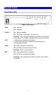
Physical Details Front-Panel LEDs Figure 2: Front Panel PWR On - Power on. Off - No power. WLAN On - Wireless enabled. Off - No Wireless connections currently exist. Flashing - Data is being transmitted or received via the Wireless access point. This includes "network traffic" as well as user data. LAN It indicates the connection of each port. If neither LED is on, there is no active connection on the corresponding LAN port. ADSL On - ADSL connection established.
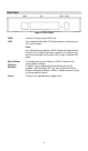
Rear Panel Figure 3: Rear Panel WAN Connect this port to your ADSL line. LAN Use standard LAN cables (RJ45 connectors) to connect your PCs to these ports. Note: Any LAN port on the Wireless ADSL Router will automatically function as an "Uplink" port when required. Just connect any port to a normal port on the other hub, using a standard LAN cable. Reset Button (Reset to Defaults) Power This button will reset the Wireless ADSL2+ Router to the factory default settings.
2 Chapter 2 Installation This Chapter covers the physical installation of the Wireless ADSL2+ Router. Requirements • Network cables. Use standard 10/100BaseT network (UTP) cables with RJ45 connectors. • TCP/IP protocol must be installed on all PCs. • For Internet Access, an Internet Access account with an ISP, and a DSL connection. • To use the Wireless Access Point, all Wireless devices must be compliant with the IEEE 802.11g or IEEE 802.11b specifications.
2. Connect LAN Cables Use standard LAN cables to connect PCs to the Switching Hub ports on the Wireless ADSL2+ Router. Both 10BaseT and 100BaseT connections can be used simultaneously. If required, connect any port to a normal port on another Hub, using a standard LAN cable. Any LAN port on the Wireless ADSL2+ Router will automatically function as an "Uplink" port when required. 3.
3 Chapter 3 Setup This Chapter provides Setup details of the WBR-3600 Router. Overview This chapter describes the setup procedure for: • Internet Access • LAN configuration • Wireless setup • Assigning a Password to protect the configuration data. PCs on your local LAN may also require configuration. For details, see Chapter 4 - PC Configuration. Other configuration may also be required, depending on which features and functions of the WBR-3600 Router you wish to use.
Use any of the following Administration Configuration settings or features: • PC Database • Config File • Logs • E-mail • Diagnostics • Remote Admin • Routing • Upgrade Firmware 10 Chapter 7 Advanced Administration
Configuration Program The WBR-3600 Router contains an HTTP server. This enables you to connect to it, and configure it, using your Web Browser. Your Browser must support JavaScript. The configuration program has been tested on the following browsers: • Netscape 7.1 or later. • Mozilla 1.6 or later • Internet Explorer V5.5 or later Preparation Before attempting to configure the WBR-3600 Router, please ensure that: • Your PC can establish a physical connection to the WBR-3600 Router.
If you can't connect If the WBR-3600 Router does not respond, check the following: • The WBR-3600 Router is properly installed, LAN connection is OK, and it is powered ON. You can test the connection by using the "Ping" command: • Open the MS-DOS window or command prompt window. • Enter the command: ping 192.168.0.1 If no response is received, either the connection is not working, or your PC's IP address is not compatible with the WBR-3600 Router's IP Address. (See next item.
Setup Wizard The first time you connect to the WBR-3600 Router, you should run the Setup Wizard to configure the ADSL and Internet Connection. 1. Click the Setup Wizard link on the main menu 2. On the first screen, select VC 1 (Router - Primary Internet Connection), then click "Next" Figure 5: Setup Wizard Home Page 3. On the VC1 screen, shown below, enter the VPI and VCI values provided by your ISP, then click "Next".
Figure 7: Setup Wizard - Internet Access 4. On the Internet Access Screen, shown above, select the correct connection type, as used by your ISP. Click "Next" and complete the configuration for your connection method. • You need the data supplied by your ISP. Your ISP's data will also have the DSL Multiplexing Method ( LLC or VC ) • The common connection types are explained in the following table..
5. Step through the Wizard until finished. 6. On the final screen of the Wizard, run the test and check that an Internet connection can be established. 7. If the connection test fails: • Check all connections, and the front panel LEDs. • Check that you have entered all data correctly.
Configuring VCs The WBR-3600 Router supports multiple VCs (Virtual Circuits) on the ADSL connection. VC1 must be used for general-purpose Internet access. The other VCs are available for special purposes, such as Video-on-Demand. You can only use these VCs if supported by your ISP and ADSL service provider. In that case, they will provide the necessary configuration data. Some ISP's allow multiple PPPoE connections. This allows multiple PCs to connect to the Internet using PPPoE client software.
ATM Service Select the multiplexing value provided by your ISP. LAN IP Enter the IP address of the device on your LAN which will receive the data on this VC. Address • For Video-on-Demand, this would be the IP address of your SetTop Box. • For VoIP, this would be the IP address of your VoIP TA. • Note that this IP address does not have to be in the same IP address range as other devices on your local LAN. 4. When finished, click "Next" and complete the Wizard. 5.
Home Screen After finishing the Setup Wizard, you will see the Home screen. When you connect in future, you will see this screen when you connect. An example screen is shown below. Figure 9: Home Screen Main Menu The main menu, on the left, contains links to the most-commonly used screen. To see the links to the other available screens, click "Advanced" or "Administration". The main menu also contains one (1) button: • Log Out - When finished, you should click this button to logout.
LAN Screen Use the LAN link on the main menu to reach the LAN screen. An example screen is shown below. Figure 10: LAN Screen Data - LAN Screen TCP/IP IP Address IP address for the WBR-3600 Router, as seen from the local LAN. Use the default value unless the address is already in use or your LAN is using a different IP address range. In the latter case, enter an unused IP Address from within the range used by your LAN. Subnet Mask The default value 255.255.255.
DHCP What DHCP Does A DHCP (Dynamic Host Configuration Protocol) Server allocates a valid IP address to a DHCP Client (PC or device) upon request. • The client request is made when the client device starts up (boots). • The DHCP Server provides the Gateway and DNS addresses to the client, as well as allocating an IP Address. • The WBR-3600 Router can act as a DHCP server. • Windows 95/98/ME and other non-Server versions of Windows will act as a DHCP client.
Wireless Screen The WBR-3600 Router's settings must match the other Wireless stations. Note that the WBR-3600 Router will automatically accept both 802.11b and 802.11g connections, and no configuration is required for this feature. To change the WBR-3600 Router's default settings for the Wireless Access Point feature, use the Wireless link on the main menu to reach the Wireless screen. An example screen is shown below.
SSID This is also called the "Network Name". • If using an ESS (Extended Service Set, with multiple access points) this ID is called an ESSID (Extended Service Set Identifier). • To communicate, all Wireless stations should use the same SSID/ESSID. Options Mode Channel No. Broadcast SSID Select the desired mode: • 802.11g & 802.11b - Both 802.11.g and 802.11b Wireless stations will be able to use the WBR-3600 Router. • 802.11g only - Only 802.11g Wireless stations can use the WBR-3600 Router.
Allow access by … Use this feature to determine which Wireless stations can use the Access Point. The options are: • All Wireless Stations - All wireless stations can use the access point, provided they have the correct SSID and security settings. • Set Stations Button Trusted Wireless stations only - Only wireless stations you designate as "Trusted" can use the Access Point, even if they have the correct SSID and security settings. This feature uses the MAC address to identify Wireless stations.
Wi-Fi Protect Setup Wi-Fi Protected Setup (WPS) is based on push-button or PIN (Personal Identification Number) entry authentication to provide strong WPA/WPA2 encryption keys to client devices. Users can push a button on the WBR-3600 router and the client device to exchange the encryption key. With a PIN, users can enter a code generated by the client device to connect to the network. View the Wi-Fi Protect Setup on the Wireless screen like the following.
Wireless Security This screen is accessed by clicking the "Configure" button on the Wireless screen. There are 5 options for Wireless security: • Disabled - no data encryption is used. • WEP - data is encrypted using the WEP standard. • WPA-PSK - data is encrypted using the WPA-PSK standard. This is a later standard than WEP, and provides much better security than WEP. If all your Wireless stations support WPA-PSK, you should use WPA-PSK rather than WEP.
WEP Wireless Security Figure 13: WEP Data - WEP Screen WEP Data Encryption WEP Data Encryption Default Key Select the desired option, and ensure the Wireless Stations use the same setting. • 64 Bit - data is encrypted, using the default key, before being transmitted. You must enter at least the default key. For 64 Bit Encryption, the key size is 10 chars in HEX (0~9 and A~F). • 128 Bit - data is encrypted, using the default key, before being transmitted. You must enter at least the default key.
WPA-PSK Wireless Security Figure 14-1: WPA-PSK Data - WPA-PSK Screen PSK Enter the PSK (network key). Data is encrypted using a key derived from the network key. Other Wireless Stations must use the same network key. The PSK must be from 8 to 63 characters in length. Encryption The WPA-PSK standard allows different encryption methods to be used. Select the desired option. Wireless Stations must use the same encryption method.
WPA2-PSK Wireless Security Figure 15-2: WPA2-PSK Data - WPA-PSK Screen PSK Enter the PSK (network key). Data is encrypted using a key derived from the network key. Other Wireless Stations must use the same network key. The PSK must be from 8 to 63 characters in length. Encryption The encryption method is AES. Wireless Stations must also use AES. If enabled the WPS then it only can support WPA-PSK and WPA2PSK encryption keys to client devices.
WPA-802.1x Wireless Security Figure 16: WPA-802.1x Data - WPA-802.1x Screen Server Address Enter the server address here. Radius Port Enter the port number used for connections to the Radius Server. Shared Key Enter the shared key. Data is encrypted using a key derived from the network key. Other Wireless Stations must use the same key. The key must be from 8 to 63 characters in length. Encryption The encryption method is TKIP. Wireless Stations must also use TKIP.
WPA2-802.1x Wireless Security Figure 17: WPA2-802.1x Data - WPA2-802.1x Screen Server Address Enter the server address here. Radius Port Enter the port number used for connections to the Radius Server. Shared Key Enter the shared key. Data is encrypted using a key derived from the network key. Other Wireless Stations must use the same key. The key must be from 8 to 63 characters in length. Encryption The encryption method is AES. Wireless Stations must also use AES.
Trusted Wireless Stations This feature can be used to prevent unknown Wireless stations from using the Access Point. This list has no effect unless the setting Allow access by trusted stations only is enabled. To change the list of trusted wireless stations, use the Modify List button on the Access Control screen. You will see a screen like the sample below.
>> Delete a Trusted Wireless Station from the list (move to the "Other Stations" list). • Select an entry (or entries) in the "Trusted Stations" list. • Click the " >> " button. Edit Use this to change an existing entry in the "Trusted Stations" list: 1. Select the Station in the Trusted Station list. 2. Click the Edit button. The address will be copied to the "Address" field, and the Add button will change to Update. 3. Edit the address (MAC or physical address) as required. 4.
Password Screen The password screen allows you to assign a password to the WBR-3600 Router. Figure 19: Password Screen Old Password Enter the existing password in this field. New password Enter the new password here. Verify password Re-enter the new password here. You will be prompted for the password when you connect, as shown below. Figure 20: Password Dialog • The "User Name" is always admin • Enter the password for the WBR-3600 Router, as set on the Password screen above.
Mode Screen Use this screen to change the mode between Router mode and Modem (Bridge) mode. Figure 21: Mode Screen Select the desired option, and click "Save". Router Both the ADSL2+ Modem and the Router features are operational. In this mode, this device can provide shared Internet Access to all your LAN users. Also, by default, it acts a DHCP Server, providing an IP address and related information to all Wireless and LAN users. Modem Only the ADSL2+ Modem component is operational.
Chapter 4 PC Configuration 4 This Chapter details the PC Configuration required on the local ("Internal") LAN. Overview For each PC, the following may need to be configured: • TCP/IP network settings • Internet Access configuration • Wireless configuration Windows Clients This section describes how to configure Windows clients for Internet access via the WBR-3600 Router. The first step is to check the PC's TCP/IP settings.
Checking TCP/IP Settings - Windows 2000: 1. Select Control Panel - Network and Dial-up Connection. 2. Right - click the Local Area Connection icon and select Properties. You should see a screen like the following: Figure 22: Network Configuration (Win 2000) 3. Select the TCP/IP protocol for your network card. 4. Click on the Properties button. You should then see a screen like the following.
5. Ensure your TCP/IP settings are correct, as described below. Using DHCP To use DHCP, select the radio button Obtain an IP Address automatically. This is the default Windows setting. Using this is recommended. By default, the WBR-3600 Router will act as a DHCP Server. Restart your PC to ensure it obtains an IP Address from the WBR-3600 Router.
Checking TCP/IP Settings - Windows XP 1. Select Control Panel - Network Connection. 2. Right click the Local Area Connection and choose Properties. You should see a screen like the following: Figure 24: Network Configuration (Windows XP) 3. Select the TCP/IP protocol for your network card. 4. Click on the Properties button. You should then see a screen like the following.
5. Ensure your TCP/IP settings are correct. Using DHCP To use DHCP, select the radio button Obtain an IP Address automatically. This is the default Windows setting. Using this is recommended. By default, the WBR-3600 Router will act as a DHCP Server. Restart your PC to ensure it obtains an IP Address from the WBR-3600 Router. Using a fixed IP Address ("Use the following IP Address") If your PC is already configured, check with your network administrator before making the following changes.
Internet Access To configure your PCs to use the WBR-3600 Router for Internet access: • Ensure that the DSL modem, Cable modem, or other permanent connection is functional. • Use the following procedure to configure your Browser to access the Internet via the LAN, rather than by a Dial-up connection. For Windows 2000 1. Select Start Menu - Settings - Control Panel - Internet Options. 2. Select the Connection tab, and click the Setup button. 3.
Macintosh Clients From your Macintosh, you can access the Internet via the WBR-3600 Router. The procedure is as follows. 1. Open the TCP/IP Control Panel. 2. Select Ethernet from the Connect via pop-up menu. 3. Select Using DHCP Server from the Configure pop-up menu. The DHCP Client ID field can be left blank. 4. Close the TCP/IP panel, saving your settings.
Wireless Station Configuration This section applies to all Wireless stations wishing to use the WBR-3600 Router's Access Point, regardless of the operating system which is used on the client. To use the Wireless Access Point in the WBR-3600 Router, each Wireless Station must have compatible settings, as follows: Mode The mode must be set to Infrastructure (rather than Ad-hoc) Access points only operate in Infrastructure mode. SSID (ESSID) This must match the value used on the WBR-3600 Router.
Figure 27 Wireless Networks (Windows XP) If the "Broadcast SSID" setting on the WBR-3600 Router has been disabled, its SSID will NOT be listed. See the following section "If the SSID is not listed" for details of dealing with this situation. 4. The next step depends on whether or not Wireless security has been enabled on the WBR-3600 Router. If Wireless Security is Disabled If Wireless security on the WBR-3600 Router is disabled, Windows will warn you that the Wireless network is not secure.
To connect: • Check the checkbox Allow me to connect to the selected wireless network, even though it is not secure. • The Connect button will then be available. Click the Connect button, and wait a few seconds for the connection to be established. If using WEP Data Encryption If WEP data encryption has been enabled on the WBR-3600 Router, Windows will detect this, and show a screen like the following.
Figure 30: Advanced - Wireless Networks Select the SSID for the WBR-3600 Router, and click Configure, to see a screen like the following: Figure 31: Wireless Network Properties - WEP Configure this screen as follows: • Set Network Authentication to match the WBR-3600 Router. (If the setting on the WBR-3600 Router is "Auto", then either Open or Shared can be used.) • For Data Encryption, select WEP.
• For the Network key and Confirm network key, enter the default key value used on the WBR-3600 Router. (Windows will determine if 64bit or 128bit encryption is used.) • The Key index must match the default key index on the WBR-3600 Router. The default value is 1. • Ensure the options The key is provided for me automatically and This is a computer-to-computer (ad hoc) network are unchecked. • Click OK to save and close this dialog.
If using WPA-PSK Data Encryption If WPA-PSK data encryption has been enabled on the WBR-3600 Router, it does not matter which network is selected on the screen below. Just click the Advanced button. Figure 33: Wireless Networks (Windows XP) You will then see a screen like the example below.
Figure 35: Wireless Network Properties- WPA-PSK Configure this screen as follows: • Set Network Authentication to WPA-PSK. • For Data Encryption, select TKIP. • For the Network key and Confirm network key, enter the network key (PSK) used on the WBR-3600 Router. • Ensure the option This is a computer-to-computer (ad hoc) network is unchecked. • Click OK to save and close this dialog. • This wireless network will now be listed in Preferred Networks on the screen below.
Click OK to establish a connection to the WBR-3600 Router. If the SSID is not listed If the "Broadcast SSID" setting on the WBR-3600 Router has been disabled, its SSID will NOT be listed on the screen below. Figure 37: Wireless Networks (Windows XP) In this situation, you need to obtain the SSID from your network administrator, then follow this procedure: 1. Click the Advanced button to see a screen like the example below.
2. Click the Add button. You will see a screen like the example below. Figure 39: Add Wireless Network 3. Configure this screen as follows: • Enter the correct SSID, as used on the WBR-3600 Router. Remember the SSID is case-sensitive, so be sure to match the case, not just the spelling. • Set Network Authentication and Data Encryption to match the WBR-3600 Router. • If using data encryption (WEP or WPA-PSK), enter the key used on the WBR3600 Router.
4. This wireless network will then be listed in Preferred Networks on the screen below. Figure 40: Preferred Networks 5. Click OK to establish a connection to the WBR-3600 Router.
Chapter 5 Operation and Status 5 This Chapter details the operation of the WBR-3600 Router and the status screens. For Details of operation in Bridge (Modem) mode, see Chapter 8 - Modem Mode. Operation - Router Mode Once both the WBR-3600 Router and the PCs are configured, operation is automatic. However, there are some situations where additional Internet configuration may be required. Refer to Chapter 6 - Advanced Features for further details.
Figure 41: Status Screen Data - Status Screen ADSL Modem Status This indicates the status of the ADSL2+ modem component. DownStream Connection Speed Displays the speed for the DownStream Connection. UpStream Connection Speed If connected, displays the speed for the Up Stream (upload) ADSL Connection. VC 1 ~ 8 Status For each VC (Virtual Circuit), the current status is displayed. This will be either "Enabled" or "Disabled". Note: VC 1 is a standard (Routed) Internet connection.
Internet (VC1) Connection Method Displays the current connection method, as set in the Setup Wizard. Connection Status This indicates the current status of the Internet Connection • Active - Connection exists • Idle - No current connection, but no error has been detected. This condition normally arises when an idle connection is automatically terminated. • Failed - The connection was terminated abnormally. This could be caused by Modem failure, or the loss of the connection to the ISP's server.
Buttons ADSL Details View the details of each VC (Virtual Circuit). Connection Details Click this button to open a sub-window and view a detailed description of the current connection. Attached Devices This will open a sub-window, showing all LAN and Wireless devices currently on the network. Refresh Screen Update the data displayed on screen.
Connection Status - PPPoE & PPPoA If using PPPoE (PPP over Ethernet) or PPPoA (PPP over ATM), a screen like the following example will be displayed when the "Connection Details" button is clicked. Figure 42: PPPoE Status Screen Data - PPPoE/PPPoA Screen Connection Time This indicates how long the current connection has been established. PPPoE Link Status This indicates whether or not the connection is currently established.
Connection Details - Dynamic IP Address If your access method is "Direct" (no login), with a Dynamic IP address, a screen like the following example will be displayed when the "Connection Details" button is clicked. Figure 43: Connection Details - Fixed/Dynamic IP Address Data - Dynamic IP address Internet IP Address The current IP Address of this device, as seen by Internet users. This address is allocated by your ISP (Internet Service Provider).
Connection Details - Fixed IP Address If your access method is "Direct" (no login), with a fixed IP address, a screen like the following example will be displayed when the "Connection Details" button is clicked. Figure 44: Connection Details - Fixed/Dynamic IP Address Data - Fixed IP address Screen Internet IP Address The IP Address of this device, as seen by Internet users. This address is allocated by your ISP (Internet Service Provider).
Chapter 6 Advanced Features 6 This Chapter explains when and how to use the WBR-3600 Router's "Advanced" Features. Overview The following advanced features are provided: • Internet: • DMZ • URL filter • Access Control • Dynamic DNS • Options • Schedule • Port Trigger • Port Foward • Port Range Forward • QoS Internet This screen provides access to the DMZ, Special Applications and URL Filter features.
DMZ This feature, if enabled, allows the DMZ computer on your LAN to be exposed to all users on the Internet. • This allows almost any application to be used on the "DMZ PC". • The "DMZ PC" will receive all "Unknown" connections and data. • If the DMZ feature is enabled, you must select the PC to be used as the "DMZ PC". The "DMZ PC" is effectively outside the Firewall, making it more vulnerable to attacks. For this reason, you should only enable the DMZ feature when required.
Data - URL Filter Screen Current Filter Strings Current Filter Strings Add Filter String The list contains the current list of items to block. • To add to the list, use the "Add" option below. • To delete an entry, select it and click Delete button. • To delete all entries, click the Delete All button. To add to the current list, type the word or domain name you want to block into the field provided, then click the Add button. Filter strings should be as specific as possible.
Access Control This feature is accessed by the Access Control link on the Advanced menu. The Access Control feature allows administrators to restrict the level of Internet Access available to PCs on your LAN. Access Control Screen To view this screen, select the Access Control link on the Advanced menu. Figure 47-1: Access Control Screen Data - Access Control Screen Internet Access Access Control Select the desired options for the current group: y Disable - No outgoing traffic is blocked.
Trusted PCs Click to enable Trusted PCs Enable this to allow one computer to have unrestricted access to the Internet. If enabled, you must select the PC to be the trusted PC. Set Trusted PCs Button Click this button to manage the trusted PC database. Trusted Wireless Stations This feature can be used to prevent unknown PCs from using the Router. This list has no effect unless the setting Allow access by trusted PCs only is enabled. You will see a screen like the sample below.
Dynamic DNS (Domain Name Server) This free service is very useful when combined with the Virtual Server feature. It allows Internet users to connect to your Virtual Servers using a URL, rather than an IP Address. This also solves the problem of having a dynamic IP address. With a dynamic IP address, your IP address may change whenever you connect, which makes it difficult to connect to you. DDNS Services work as follows: 1. You must register for the service at one of the listed DDNS Service providers. 2.
Data - Dynamic DNS Screen DDNS Service Use a Dynamic DNS Service Use this to enable or disable the DDNS feature as required. Service Provider Select the desired DDNS Service provider. Web Site Click this button to open a new window and connect to the Web site of the selected DDNS service provider. DDNS Data Host Name Enter the domain name allocated to you by the DDNS Service. If you have more than one name, enter the name you wish to use. User Name Enter your Username for the DDNS Service. (TZO.
Options This screen allows advanced users to enter or change a number of settings. For normal operation, there is no need to use this screen or change any settings. An example Options screen is shown below. Figure 50: Options Screen Data - Options Screen Internet Respond to Ping MTU Size • If checked, the Wireless Router will respond to Ping (ICMP) packets received from the Internet. • If not checked, Ping (ICMP) packets from the Internet will be ignored.
Schedule This Schedule can be used for the Firewall Rules and the URL filter. Figure 51: Schedule Screen Data - Schedule Screen Schedule Day Each day of the week can scheduled independently. Session 1 Two (2) separate sessions or periods can be defined. Session 2 can be left blank if not required. Session 2 Start Time Enter the start using a 24 hr clock. Finish Time Enter the finish time using a 24 hr clock.
Port Trigger If you use Internet applications which use non-standard connections or port numbers, you may find that they do not function correctly because they are blocked by the WBR-3600 Router's firewall. In this case, you can define the application as a "Port Trigger". The Port Trigger screen can be reached by clicking the Port Trigger on the screen. You can then define your Port Trigger.
Data - Port Trigger Screen Port Trigger Enable Use this to Enable or Disable this Special Application as required. Name Enter a descriptive name to identify this Special Application. Outgoing Ports Incoming Ports • Type - Select the protocol (TCP or UDP) used when you send data to the remote system or service. • Start - Enter the beginning of the range of port numbers used by the application server, for data you send to it.
Port Forward This feature allows you to make Servers on your LAN accessible to Internet users. Normally, Internet users would not be able to access a server on your LAN because: • Your Server does not have a valid external IP Address. • Attempts to connect to devices on your LAN are blocked by the firewall in this device. Figure 53: Port Forwarding Screen Data - Port Forwarding Screen Port Forwarding Application Enter the desired application type.
Port Range Forward This feature allows you to make Servers on your LAN accessible to Internet users. Normally, Internet users would not be able to access a server on your LAN because: Figure 54: Port Range Forwarding Screen Data - Port Range Forwarding Screen Port Range Forwarding Application Enter the desired application type. Start Enter the beginning of the range of port numbers used by the application server. End Enter the end of the range of port numbers used by the application server.
QoS The QoS (Quality of Service) feature allows you specify priorities for different traffic. Lower priority traffic will be slowed down to allow greater throughput or less delay for high priority traffic. An example QoS screen is shown below. Figure 55: QoS Screen Data - QoS Screen QoS Setting QoS Setting To disable QoS (Quality of Service), keep the default setting, Disable. To enable QoS (Quality of Service), click Enable and follow these instructions.
Category • • Applications: • Add a New Application (Once selected, please complete the following setups.) • Ip/Net: Enter the IP address. • Rate: Enter the desired rate value. • Priority: Select the desired option (High, Normal, Low) • Direct: Select Upstream or Downstream as required. Self-Define • Name. Enter a name for your device. • Port Range: Enter the value for the desired port range. • Protocol: Select the desired option. • Ip/Net: Enter the IP address of your device.
Chapter 7 Advanced Administration 7 This Chapter explains the settings available via the "Administration" section of the menu. Overview Normally, it is not necessary to use these screens, or change any settings. These screens and settings are provided to deal with non-standard situations, or to provide additional options for advanced users. The available settings and features are: PC Database This is the list of PCs shown when you select the "DMZ PC" or a "Virtual Server".
PC Database The PC Database is used whenever you need to select a PC (e.g. for the "DMZ" PC). • It eliminates the need to enter IP addresses. • Also, you do not need to use fixed IP addresses on your LAN. However, if you do use a fixed IP address on some devices on your LAN, you should enter details of each such device into the PC database, using the PC Database screen. PC Database Screen An example PC Database screen is shown below.
Config File This feature allows you to download the current settings from the WBR-3600 Router, and save them to a file on your PC. You can restore a previously-downloaded configuration file to the WBR-3600 Router, by uploading it to the WBR-3600 Router. This screen also allows you to set the WBR-3600 Router back to its factory default configuration. Any existing settings will be deleted. An example Config File screen is shown below.
Logs The Logs record various types of activity on the WBR-3600 Router. This data is useful for troubleshooting, but enabling all logs will generate a large amount of data and adversely affect performance. Since only a limited amount of log data can be stored in the WBR-3600 Router, log data can also be E-mailed to your PC. Use the E-mail screen to configure this feature. Figure 58: Logs Screen Data - Logs Screen Logs Current Time The current time on the WBR-3600 Router is displayed.
Include in Log Include (Checkboxes) Use these checkboxes to determine which events are included in the log. Checking all options will increase the size of the log, so it is good practice to disable any events which are not really required. • Attempted access to blocked sites - If checked, attempted Internet accesses which were blocked are logged.
E-mail This screen allows you to E-mail Logs and Alerts. A sample screen is shown below. Figure 59: E-mail Screen Data - E-mail Screen E-Mail Notification Turn E-mail Notification on Check this box to enable this feature. If enabled, the E-mail address information (below) must be provided. Send to this Email address Enter the E-mail address the Log is to be sent to. The E-mail will also show this address as the Sender's address.
E-mail Alerts Send E-mail alerts immediately You can choose to have alerts E-mailed to you, by checking the desired checkboxes. The WBR-3600 Router can send an immediate alert when it detects a significant security incident such as • A known hacker attack is directed at your IP address • A computer on the Internet scans your IP address for open ports • Someone on your LAN (Local Area Network) tries to visit a blocked site.
Diagnostics This screen allows you to perform a "Ping" or a "DNS lookup". These activities can be useful in solving network problems. An example Network Diagnostics screen is shown below. Figure 60: Network Diagnostics Screen Data - Network Diagnostics Screen Ping Ping this IP Address Enter the IP address you wish to ping. The IP address can be on your LAN, or on the Internet. Note that if the address is on the Internet, and no connection currently exists, you could get a "Timeout" error.
Remote Administration If enabled, this feature allows you to manage the WBR-3600 ADSL2+ Router via the Internet. Figure 61: Remote Administration Screen Data - Remote Administration Screen Remote Administration Enable Remote Management Check to allow administration/management via the Internet. (To connect, see below). If Disabled, this device will ignore Administration connection attempts from the Internet.
IP address to define the allowed range. For security, you should restrict access to as few external IP addresses as practical. To connect from a remote PC via the Internet 1. Ensure your Internet connection is established, and start your Web Browser. 2. In the "Address" bar, enter "HTTP://" followed by the Internet IP Address of the WBR-3600 Router. If the port number is not 80, the port number is also required. (After the IP Address, enter ":" followed by the port number.) e.g. HTTP://123.123.123.
Routing Overview • If you don't have other Routers or Gateways on your LAN, you can ignore the "Routing" page completely. • If the WBR-3600 Router is only acting as a Gateway for the local LAN segment, ignore the "Routing" page even if your LAN has other Routers. • If your LAN has a standard Router (e.g. Cisco) on your LAN, and the WBR-3600 Router is to act as a Gateway for all LAN segments, enable RIP (Routing Information Protocol) and ignore the Static Routing table.
Figure 62: Routing Screen Data - Routing Screen RIP RIP Direction Select the desired RIP Direction. RIP Version Select RIP-1/RIP-2B/RIP-2M from the drop down list box. Static Routing Static Routing Table Entries This list shows all entries in the Routing Table. • This area shows details of the selected item in the list. • Change any the properties as required, then click the "Edit" button to save the changes to the selected entry.
Configuring Other Routers on your LAN It is essential that all IP packets for devices not on the local LAN be passed to the WBR-3600 Router, so that they can be forwarded to the external LAN, WAN, or Internet. To achieve this, the local LAN must be configured to use the WBR-3600 Router as the Default Route or Default Gateway. Local Router The local router is the Router installed on the same LAN segment as the WBR-3600 Router. This router requires that the Default Route is the WBR-3600 Router itself.
Static Routing - Example Figure 63: Routing Example For the WBR-3600's Routing Table For the LAN shown above, with 2 routers and 3 LAN segments, the WBR-3600 Router requires 2 entries as follows. Entry 1 (Segment 1) Destination IP Address 192.168.1.0 Network Mask 255.255.255.0 (Standard Class C) Gateway IP Address 192.168.0.100 (WBR-3600 Router's local Router) Metric 2 Entry 2 (Segment 2) Destination IP Address 192.168.2.0 Network Mask 255.255.255.0 (Standard Class C) Gateway IP Address 192.
Upgrade Firmware The firmware (software) in the WBR-3600 Router can be upgraded using your Web Browser. You must first download the upgrade file, then select Upgrade Firmware on the Administration menu. You will see a screen like the following. Figure 64: Router Upgrade Screen To perform the Firmware Upgrade: 1. Click the Browse button and navigate to the location of the upgrade file. 2. Select the upgrade file. Its name will appear in the Upgrade File field. 3.
8 Chapter 8 Modem Mode This Chapter explains configuration and operation when in "Modem" or "Bridge" mode”. Overview There are two modes available on the Mode screen. • Router - Both the ADSL2+ Modem and the Router features are operational. In this mode, this device can provide shared Internet Access to all your LAN users. Also, by default, it acts a DHCP Server, providing an IP address and related information to all Wireless and LAN users. • Modem - Only the ADSL2+ Modem component is operational.
Home Screen If in Modem mode, the home screen will look like the example below. Figure 65: Home Screen - Modem Mode Note that the menu has changed, many of the options in Router mode are not available. The screens available are: • Mode - change back to Router mode, if desired. • LAN - set IP address, mask and gateway. This is the same as in Router mode, except that the DHCP server is not available while in Modem mode. • Wireless - this screen, and related sub-screens, is the same as in Router mode.
Mode Screen This screen is change back to Router mode, if desired. Figure 66: Mode Screen Data - Mode Screen Device Name This field displays the current name of this device. Device Mode Select the desired device mode for the router: • Router - Both the ADSL2+ Modem and the Router features are operational. In this mode, this device can provide shared Internet Access to all your LAN users.
Status Screen In Modem mode, the Status screen looks like the example below. Figure 67: Status Screen - Bridge Mode Data - Status Screen (Bridge Mode) ADSL Modem Status This indicates the status of the ADSL2+ modem component. DownStream Connection Speed Displays the speed for the DownStream Connection. UpStream Connection Speed If connected, displays the speed for the Up Stream (upload) ADSL Connection.
LAN IP Address The IP Address of the WBR-3600 Router. Network Mask The Network Mask (Subnet Mask) for the IP Address above. MAC Address This shows the MAC Address for the WBR-3600 Router, as seen on the LAN interface. Wireless Name (SSID) If using an ESS (Extended Service Set, with multiple access points) this ID is called an ESSID (Extended Service Set Identifier). Region The current region, as set on the Wireless screen.
Appendix A Troubleshooting A This Appendix covers the most likely problems and their solutions. Overview This chapter covers some common problems that may be encountered while using the WBR-3600 Router and some possible solutions to them. If you follow the suggested steps and the WBR-3600 Router still does not function properly, contact your dealer for further advice. General Problems Problem 1: Can't connect to the WBR-3600 Router to configure it.
and power connections.) • Check the WBR-3600 Router's status screen to see if it is working correctly. Problem 2: Some applications do not run properly when using the WBR-3600 Router Solution 2: The WBR-3600 Router processes the data passing through it, so it is not transparent. For incoming connections, you must use the Virtual Server or Firewall Rules to specify the PC which will receive the incoming traffic. You can also use the DMZ function.
devices should be shielded or relocated. • RF Shielding Your environment may tend to block transmission between the wireless stations. This will mean high access speed is only possible when close to the WBR-3600 Router.
Appendix B About Wireless LANs B This Appendix provides some background information about using Wireless LANs (WLANs). Modes Wireless LANs can work in either of two (2) modes: • Ad-hoc • Infrastructure Ad-hoc Mode Ad-hoc mode does not require an Access Point or a wired (Ethernet) LAN. Wireless Stations (e.g. notebook PCs with wireless cards) communicate directly with each other. Infrastructure Mode In Infrastructure Mode, one or more Access Points are used to connect Wireless Stations (e.g.
performance. This capability is called Roaming. (Access Points do not have or require Roaming capabilities.) Channels The Wireless Channel sets the radio frequency used for communication. • Access Points use a fixed Channel. You can select the Channel used. This allows you to choose a Channel which provides the least interference and best performance. In the USA and Canada, 11 channels are available.
The same encryption method must be used. The most common encryption method is TKIP. Another widelysupported method is AES. Encryption WPA-802.1x This version of WPA requires a Radius Server on your LAN to provide the client authentication according to the 802.1x standard. Data transmissions are encrypted using the WPA standard. If this option is used: • The Access Point must have a "client login" on the Radius Server. • Each user must have a "user login" on the Radius Server.
C Appendix C Specifications Multi-Function 11g Wireless ADSL2+ Router Model WBR-3600 11g Wireless ADSL2+ Router ADSL Interface MultiMode, T1.413, G.DMT, G.lite, ADSL2, ADSL2+ Operating Temperature 0° C to 40° C Storage Temperature -10° C to 70° C Network Protocol: TCP/IP Network Interface: 4 * 10/100BaseT (RJ45) LAN connection 1 * RJ11 for ADSL line LEDs 8 Power Adapter 12VDC 1A External Wireless Interface Standards IEEE802.11b, IEEE802.11g Frequency 2.4 to 2.