
Instructions / Assembly

PK-A3214-10-00-0D
For Technical Assistance Call: 1-800-824-3005 (USA Only)
or 1-800-405-5320 (Canada Only) www.leviton.com
PK-A3214-10-00-0D
IMPORTANT SAFETY INSTRUCTIONS - READ ALL INSTRUCTIONS BEFORE USING.
INSTALLATION INSTRUCTIONS
Nos. LP2xx, LP3xx, LP4xx, LP6xx
© 2019 Leviton Mfg. Co., Inc.
Load Center Enclosure
Patents covering this product, if any, can be found on Leviton.com/patents.
LIMITED PRODUCT WARRANTY
For Leviton’s limited product warranty, go to www.leviton.com. For a printed copy of the warranty you may call 1-800-323-8920.
WARNING
INSTALLATION
WARNING: TO AVOID FIRE, SHOCK OR DEATH: TURN OFF
POWER SUPPLYING THIS EQUIPMENT, AND CONFIRM
POWER IS OFF, before installing, removing or servicing this
equipment.
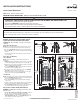
Step 1: Enclosure Knockouts
NOTE: Before removing any knockouts from the enclosure, consult
the local electrical code to determine the knockout requirements.
a. To remove knockouts (A), first strike the center of the knockout.
b. Pry each ring (B) up, one at a time, and grip both ends with a pair
of pliers.
c. Use the pliers to bend the rings until they disconnect from the
enclosure (fig. 1).
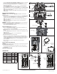
Step 2: Enclosure Mounting
Surface Mounting
NOTE: Leviton
®
load centers can be inverted for bottom feed
applications.
a. Keyholes (C) at the top and bottom of the enclosure are provided
to assist in the alignment and leveling of the enclosure (fig. 2).
b. Temporary screws or nails (not provided) should be used in these
keyholes during alignment and leveling.
c. Four (x4) mounting holes (D) have been precut in the back of the
enclosure for ease of installation (fig. 2).
d. Use screws or nails (not provided) in these four (x4) mounting
holes (D) to secure the enclosure to the wall.
e. Remove the temporary screws or nails that were used to align
and level the enclosure through the keyholes (C).
Flush Mounting
NOTE:
Leviton load centers can be inverted for bottom feed applications.
a. Four (x4) mounting slots (E) have been precut on the side of the
enclosure for installation between studs.
b. Pierce the foil tape (F) on side of enclosure with a mounting
screw or nail.
c. If using 1/2 inch sheetrock, align the embossed (1/2) line with the
front of the stud to achieve optimal flush mounting (fig. 3).
d. Use the mounting slots (E) on both sides of enclosure to mount
the enclosure with screws or nails (not provided) (fig. 3).
Step 3: Phase, Neutral and Ground Conductors
WARNING: Use ONLY approved fittings and clamps to avoid
damage to wires.
a. Bring the phase wires (G), neutral (H) and ground (I) conductors
into the enclosure through the predetermined knockouts.
b. Determine whether or not the application requires the use of a
main circuit breaker (J) (fig. 4), or if main lugs (K) (fig. 5) can
be used based on the local electrical codes.
Fig. 1
Fig. 2 Fig. 3
a. b. c.
• TO AVOID FIRE, SHOCK OR DEATH: TURN OFF POWER SUPPLYING THIS EQUIPMENT, AND CONFIRM POWER IS OFF,
before installing, removing or servicing this equipment.
• This equipment MUST BE installed and serviced by an electrician.
• Replace all doors and covers before connecting power to this equipment.
• To be installed and/or used in accordance with electrical codes and regulations.
Knockouts
(A)
Rings
(B)
Rings
(B)
Foil tape
(F) (x4)
Mounting slots
(E) (x4)
1/2 in. line
Keyhole (C)
Mounting
holes
(D) (x4)
Keyhole (C)
WEB VERSION