LCD TV PLASMA TV MODELS: 32LC2D 32LC2DU 37LC2D 42LC2D MODELS: 42PC3D 42PC3DC 42PC3DV 50PC3D 60PC1D 60PC1DC OWNER’S MANUAL Internet Home Page : http://www.lge.com http://www.lg.ca http://www.lgcommercial.com ENERGYSTAR is a set of power-saving guidelines issued by the U.S. Environmental Protection Agency(EPA). As an ENERGY STAR Partner LGE U. S. A.,Inc. has determined that this product meets the ENERGY STAR guidelines for energy efficiency. Please read this manual carefully before operating your set.
Warning Warning CAUTION RISK OF ELECTRIC SHOCK DO NOT OPEN WARNING: TO REDUCE THE RISK OF ELECTRIC SHOCK DO NOT REMOVE COVER (OR BACK). NO USER SERVICEABLE PARTS INSIDE. REFER TO QUALIFIED SERVICE PERSONNEL. The lightning flash with arrowhead symbol, within an equilateral triangle, is intended to alert the user to the presence of uninsulated “dangerous voltage” within the product’s enclosure that may be of sufficient magnitude to constitute a risk of electric shock to persons.
Safety Instructions Safety Instructions WARNING : To reduce the risk of fire or electric shock, do not expose this apparatus to rain or moisture. Apparatus shall not be exposed to dripping or splashing and no objects filled with liquids, such as vases, shall be placed on the apparatus. IMPORTANT SAFETY INSTRUCTIONS 1. Read these instructions. Ow ner's Man ual 2. Keep these instructions. 8.
Safety Instructions 12. Use only with a cart, stand, tripod, bracket, or table specified by the manufacturer, or sold with the apparatus. When a cart is used, use caution when moving the cart / apparatus combination to avoid injury from tip-over. 14. Refer all servicing to qualified service personnel.
Contents Introduction Contents 2 Warning 3~4 Safety Instructions 7 Accessories 8~11 Controls Connection Options Operation Installation 12~13 Remote Control Key Functions 14 15 16~17 Attaching the TV to a wall Desktop Pedestal Installation Basic Connection 18 19~20 20 21~22 23~24 25 25 26~28 Antenna or Cable Connection VCR Setup External AV Source Setup DVD Setup HDSTB Setup AV Out Setup Digital Audio Output PC Setup Basic operation 29 29 29 29 30 Turning on the TV Volume Adjustment Channe
Contents Operation Time Menu Options Option Menu Features Reference Lock Menu Options 6 44 44 45 45 46 Manual Clock Setup Auto Clock Setup On/Off Timer Setup Sleep Timer Auto Off 47 48 49 49 50 Aspect Ratio Control Caption/Text Caption Option Low Power (42PC3D/3DC/3DV, 50PC3D, 60PC1D/1DC Only) ISM (Image Sticking Minimization) Method (42PC3D/3DC/3DV, 50PC3D, 60PC1D/1DC Only) 51~52 Parental Lock Setup 53~58 External Control Device Setup 59~60 IR Codes 61 Programming the Remote 62~63 Progr
Introduction Introduction Accessories TV Ensure that the following accessories are included with your TV. If any accessory is missing, please contact the dealer from where you purchased the product. User must use shielded signal interface cables(D-sub 15 pin cable) with ferrite cores to maintain standard compliance for the product.
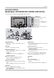
Introduction Controls (Model Name: 42PC3D/3DC/3DV, 50PC3D, 60PC1D/1DC) - This is a simplified representation of front panel. - This picture shown below may be somewhat different from your TV. 42PC3D/3DC/3DV, 50PC3D CHANNEL (D, Buttons CH E) VOLUME (F,G) Buttons VOL OL ENTER ENTER Button MENU MENU Button INPUT INPUT Button Remote Control Sensor (Power) Button Power/Standby Indicator • illuminates red in standby mode. • illuminates green when the set is switched on.
Introduction Connection Options (Model Name: 42PC3D/3DC/3DV, 50PC3D, 60PC1D/1DC) - This picture shown below may be somewhat different from your TV. AV IN 2 R /MONO S-VIDEO Input Provides better picture quality than the video input. AUDIO Input Connections are available for listening to stereo sound from an external device. VIDEO Input Connects the video signal from a video device.
Introduction Controls (Model Name: 32/37/42LC2D, 32LC2DU) - This is a simplified representation of front panel. - This picture shown below may be somewhat different from your TV. CH VOL ENTER CHANNEL (D, Buttons E) VOLUME (F,G) Buttons ENTER Button MENU MENU Button INPUT INPUT Button R (Power) Button Remote Control Sensor Power/Standby Indicator • illuminates red in standby mode. • illuminates green when the set is switched on.
( S-VIDEO VIDEO ) AUDIO AV OUT AV IN 1 COMPONENT IN AUDIO VIDEO COMPONENT IN AUDIO VIDEO Introduction AV OUT AV IN 1 Connection Options (Model Name: 32/37/42LC2D, 32LC2DU) ( S-VIDEO VIDEO ) AUDIO - This picture shown below may be somewhat different from your TV. S-VIDEO Input Provides better picture quality than the video input. VIDEO Input Connects the video signal from a video device. AUDIO Input Connections are available for listening to stereo sound from an external device.
Introduction Remote Control Key Functions POWER Turns your TV or any other programmed equipment on or off, depending on mode. INPUT TV INPUT POWER DVD TV CABLE AUDIO INPUT VCR MODE TV INPUT In AV1-2, Component 1-2, or RGB-PC, HDMI1/DVI, and HDMI2 input sources, screen returns to the last TV channel. External input modes rotate in regular sequence: TV, AV1-2, Component 1-2, RGB-PC, HDMI1/DVI or HDMI2.
Introduction INPUT TV INPUT POWER DVD TV VCR MODE CABLE AUDIO VCR/DVD/DVHS/Camcorder BUTTONS Control some video cassette recorders or DVD players ("RECORD" button is not available for DVD player). STB VOLUME UP/DOWN Increases/decreases the sound level. CHANNEL UP/DOWN Selects available channels found with EZ scan and Manual scan. T- BRIGH MENU BRIGH T + FAV Use to scroll the Favorite channels. ENTER EXIT TIMER MUTE G p.29 Switches the sound on or off.
Introduction Remote control effective range Installing Batteries 32/37/42LC2D, 32LC2DU INPUT TV INPUT ■ Open the battery compartment cover on the back side and install the batteries matching correct polarity (+with +,-with -). ■ Install two 1.5V AA batteries. Don’t mix old or used batteries with new ones. ■ Close cover.
Installation Installation DESKTOP PEDESTAL INSTALLATION For proper ventilation, allow a clearance of 4inches on each side from the wall. 42PC3D/3DC/3DV, 50PC3D, 60PC1D/1DC 4 inches 4 inches 4 inches 32/37/42LC2D, 32LC2DU 4 inches 4 inches 4 inches 4 inches 4 inches CAUTION G ■ Ensure adequate ventilation by following the clearance recommendations. This picture shown below may be somewhat different from your TV.
Basic Connection (For 32/37/42LC2D, 32LC2DU) 1 Connect the cables as necessary. After connecting the cables neatly, arrange the cables to the Cable Holder. To connect an additional equipment, see the External equipment Connections section. Cable holder 32LC2D/U 2 CABLE MANAGEMENT Reinstall the CABLE MANAGEMENT as shown. 32LC2D/U 3 37/42LC2D 37/42LC2D Bundle the cables using the supplied twister holder.
Basic Connection How to use stand (For 42PC3D/3DC/3DV) 1 Place the set with the screen facing down on a cushion or soft cloth as shown. Before unfolding the stand, please make sure two locks (A) on the bottom of the stand push outward. 2 Pull the stand out as shown. After unfolding the stand, please insert and tighten the screws (provided as parts of the product) in the holes (B) on the bottom of the stand. (A) (B) 3 When connecting cables to the set, Do not disengage the lock (C).
Installation External Equipment Connections NOTE: All cables shown are not included with the TV Antenna Or Cable Connection Analog and Digital TV signals provided on antenna - Antenna or Cable Service without a Cable Box Connection. - For optimum picture quality, adjust antenna direction if needed. Multi-family Dwellings/Apartments (Connect to wall antenna socket) Wall Antenna Socket OPTICAL ANTENNA/ CABLE IN DIGITAL AUDIO OUT RF Coaxial Wire (75 ohm) VHF Antenna Turn clockwise to tighten.
Installation VCR Setup - To avoid picture noise (interference), leave an adequate distance between the VCR and TV. - Typically a frozen still picture from a VCR. If the 4:3 picture format is used; the fixed images on the sides of the screen may remain visible on the screen. When connecting with an antenna 2 1 Connect the RF antenna out socket of the VCR to the Antenna socket on the set. 2 Connect the antenna cable to the RF antenna in socket of the VCR.
Installation ( S-VIDEO VIDEO ) AUDIO AV OUT AV IN 1 OPTICAL DIGITAL AUDIO OUT COMPONENT IN AUDIO VIDEO When connecting with an S-Video cable VCR 1 Connect the S-VIDEO output of the VCR to the SVIDEO input on the set. The picture quality is improved; compared to normal composite (RCA cable) input. 2 Connect the audio outputs of the VCR to the AUDIO input jacks on the set. 3 Insert a video tape into the VCR and press PLAY on the VCR. (Refer to the VCR owner’s manual.
HDMI / DVI IN ANTENNA/ CABLE IN COMPONENT IN AUDIO VIDEO Installation DVD Setup When connecting with a S-Video cable DVD (R) AUDIO (L) S-VIDEO 1 2 COMPONENT IN AUDIO VIDEO AV V OUT AV V IN 1 OPTICAL PTICAL DIGITAL AUDIO DIGITAL OUT (MONO) S-VIDEO VIDEO AUDIO 1 Connect the S-VIDEO output of the DVD to the S-VIDEO input on the set. 2 Connect the audio outputs of the DVD to the AUDIO input jacks on the set. 3 Turn on the DVD player, insert a DVD.
Installation When connecting with a component cable DVD B R (R) AUDIO (L) HDMI / DVI IN ANTENNA/ CABLE IN 2 VIDEO AUDIO COMPONENT IN 1 1 Connect the video outputs (Y, PB, PR) of the DVD to the COMPONENT IN VIDEO jacks on the set. 2 Connect the audio outputs of the DVD to the COMPONENT IN AUDIO jacks on the set. 3 Turn on the DVD player, insert a DVD. 4 Select Component 1 input source with using the INPUT button on the remote control.
Installation HDSTB Setup - This TV can receive Digital Over-the-air/Cable signals without an external digital set-top box. However, if you do receive Digital signals from a digital set-top box or other digital external device, refer to the figure as shown below. When connecting with a HDMI cable SERVICE RGB IN (PC) REMOTE CONTROL IN 1 Connect the HDMI output of the digital set-top box to the HDMI IN 1(DVI) or 2 jack on the set.
1(DVI) RS-232C IN (CONTROL & SERVICE) Installation ( S-VIDEO VIDEO ) AUDIO AV OUT AV IN 1 OPTICAL DIGITAL AUDIO OUT COMPONENT IN AUDIO VIDEO When connecting with a HDMI to DVI cable SERVICE RGB IN (PC) AUDIO IN (RGB/DVI) REMOTE CONTROL IN HDMI IN 2 1(DVI) RS-232C IN (CONTROL & SERVICE) SERVICE) 2 1 DVI-DTV OUTPUT (R) AUDIO (L) Digital Set-top Box 1 Connect the DVI output of the digital set-top box to the HDMI IN 1(DVI) jack on the set.
Installation AV Out Setup - The TV has a special signal output capability which allows you to hook up a second TV or monitor. AUDIO (MONO) S-VIDEO VIDEO AUDIO AV V OUT AV V IN 1 OPTICAL PTICAL DIGITAL AUDIO DIGITAL OUT COMPONENT IN VIDEO 1 Connect the second TV or monitor to the TV’s AV OUT jacks. 2 See the Operating Manual of the second TV or monitor for further details regarding that device’s input settings.
RGB IN (PC) AUDIO IN (RGB/DVI) REMOTE CONTROL IN Installation RS-232C IN (CONTROL & SERVICE) PC Setup - This TV provides Plug and Play capability, meaning that the PC adjusts automatically to the TV's settings. When connecting with a D-sub 15 pin cable RGB IN (PC) AUDIO IN (RGB/DVI) 1 Connect the RGB output of the PC to the RGB IN (PC) jack on the set. 2 Connect the PC audio outputs to the AUDIO IN(RGB/DVI) jack on the set. 3 Turn on the PC and the set.
Installation 1. Depending on the graphics card, DOS mode may not work if a HDMI to DVI Cable is in use. 2. When Source Devices connected with HDMI/DVI Input, output PC Resolution (VGA, SVGA, XGA, WXGA), Position and Size may not fit to Screen.Press the ADJUST button to adjust the screen Position of TV SET and contact an PC graphics card service center. 3.
Installation Screen Setup for PC mode - When RGB connect to PC input and select the RGB-PC, this function is used. - When HDMI/DVI connect to PC input and select HDMI/DVI input, this function is used. - After connecting RGB-PC or HDMI/DVI to PC input and checking the screen quality. * Adjustment for screen Resolution, Position, Size, and Phase 4 5 7 8 9 0 FLASHBK EZ PIC EZ SOUND 6 SAP CC ADJUST ADJUST 1 Press the ADJUST button and then use D Resolution, POSITION, SIZE, or PHASE.
Operation Operation Basic operation Turning on the TV 1. First, connect power cord correctly. At this moment, the TV switches to standby mode. In standby mode to turn TV on, press the , INPUT, CH D / E button on the TV or press the POWER, TV INPUT, INPUT, CH D / E, Number (0 ~ 9) button on the remote control . 2. Select the viewing source by using TV INPUT, INPUT button on the remote control. This TV is programmed to remember which power state it was last set to, even if the power cord is out. 3.
Operation On Screen Menus Selection and Adjustment How to adjust the OSD screen 1. Press the MENU button and then D 2. Press the G button and then use D /E /F /G / E button to select each menu. button to display the available menus.
Operation Setup Menu Options EZ Scan (Channel Search) EZ Scan EZ Scan Manual Scan Manual Scan Channel Edit Channel Edit DTV Signal DTV Signal Input Source Input Source Input Label Input Label Set ID Set ID Selection ( G or ) leads you to the EZ scan screen. G Processing EZ scan... TV Ch.20 0 channel(s) found Press to stop the current scan and start DIGITAL ANTENNA channel scan.
Operation Channel Edit EZ Scan EZ Scan Manual Scan Manual Scan Channel Edit Channel Edit DTV Signal DTV Signal Input Source Input Source Input Label Input Label Set ID Set ID G Selection ( G or ) leads you to the channel edit screen. * Custom List D E - There are two different ways in order to add or delete scanned channels. One is "Custom List" and the other is "Favorite List" in the channel list. Both of them are available after EZ Scan on the SETUP menu.
Operation Setup Menu Options continued DTV Signal Strength EZ Scan EZ Scan Manual Scan Manual Scan Channel Edit Channel Edit DTV Signal DTV Signal Input Source Input Source Input Label Input Label Set ID Set ID - Shows how strong your DTV signal is and whether you need to adjust your antenna or digital cable input. The higher the signal strength, the less likely you are to experience picture degradation. - DTV Signals: Only when the input signal is DTV or CADTV, this function is available.
Operation Input Label EZ Scan EZ Scan Manual Scan Manual Scan Channel Edit Channel Edit DTV Signal DTV Signal Input Source Input Source Input Label Input Label Set ID Set ID - Sets a label to each input source or lets you skip the input source which is not in use when you press INPUT button. 34 1 2 3 AV1 Cable Box AV2 VCR Component1 DVD Component2 Set Top Box RGB-PC G PC HDMI1/DVI Game HDMI2 Satellite Press the MENU button and then use D / E button to select the SETUP menu.
Operation V ideo Menu Options Auto Picture Control ( EZ Picture) - EZ Picture adjusts the TV for the best picture appearance. Select the preset value in the EZ Picture menu based on the program category. - Daylight, Normal, Night Time settings are preset for optimum picture quality at the factory and are not adjustable. - In the User 1, and User 2 modes only, user can directly adjust the contrast, brightness, color, sharpness, tint.
Operation Manual Color Temperature Control EZ Picture EZ Picture Color Temperature Color Temperature Cool XD XD Medium Advanced Advanced Warm Video Reset Video Reset User G Selection ( G or ) leads you to the detailed setting screen. Red User 0 E Red 0 Green 0 Blue 0 Press - You can also adjust the detailed set tings(Red, Green, Blue) by selecting the User menu. to confirm. 1 Press the MENU button and then use VIDEO menu. 2 Temperature .
Operation XD EZ Picture EZ Picture Color Temperature Color Temperature XD XD Advanced Advanced Video Reset Video Reset - XD is LG Electronic’s unique picture improving technology to display a real HD source through an advanced dig-ital signal processing algorithm. - When selecting EZ Picture options (Daylight, Normal and Night time), XD is automatically change to Auto.
Operation Advanced-Cinema 3:2 Mode / Black Level EZ Picture EZ Picture Color Temperature Color Temperature XD XD Advanced Advanced Video Reset Video Reset • Cinema 3:2 Mode - Set up the TV for the best picture appearance for viewing movies. When you operate Cinema (3:2 PullDown Mode or Cinema Correction Mode),the TV will adjust 24 fps video from movies to 30 fps video for display (This function is only available in Analog, AV1, AV2, Component 480i mode.
Operation Video Reset EZ Picture EZ Picture Color Temperature Color Temperature XD XD Advanced Advanced Video Reset Video Reset - Use to quickly reset all the Video menu options to their original factory preset values. 1 2 3 G Selection ( G or ) resets to the factory settings (default). Press the MENU button and then use D / E button to select the VIDEO menu. Press the G button and then use D /E button to select Video Reset.
Operation Audio Menu Options Audio Language Audio Language Audio Language EZ Sound EZ Sound Balance Balance TV Speaker TV Speaker - Other languages may be available if a digital signal is provided by the broadcasting station. 40 G English Spanish French 1 Press the MENU button and then use AUDIO menu. 2 Press the G button and then use D / E button to select Audio Language. 3 Press the G button and then use Spanish, or French.
Operation Auto Sound Control ( EZ - EZ Sound lets you enjoy the best sound without any special adjustment because the TV sets the appropriate sound options based on the program content. 1 Sound) Press the EZ SOUND button repeatedly to select the appropriate sound setup as shown below : Normal, Stadium, News, Music, Theater and User (your own settings) . • You can also adjust EZ Sound in the AUDIO menu.
Operation * Selecting the Front Surround Press the G button and then use F / G button to select Off or SRS (Sound Retrieval System) TruSurround XT . Front Surround SRS TruSurround XT Note: When SRS (Sound Retrieval System) TruSurround XT is selected, Audio Balance function is disable and set to 0 . When Off is selected, Audio Balance function is enable and reset the balance as previous. 6 Press EXIT button to return to TV viewing or press MENU button to return to the previous menu.
Operation Balance - Adjust the sound in your preference and surrounded environment. Audio Language Audio Language EZ Sound EZ Sound Balance Balance TV Speaker TV Speaker 0 L R Press the MENU button and then use D / E button to 1 select the AUDIO menu. 2 Press the G button and then use D / E button to select Balance. Balance 3 Press the G button and then use appropriate adjustments.
Operation T ime Menu Options Manual Clock Setup Auto Clock Auto Clock Manual Clock Manual Clock Off Timer Off Timer On Timer On Timer Sleep Timer Sleep Timer Auto Off Auto Off - If current time setting is wrong, reset the clock manually. 1 2 G Year Date Time --- ---/ -: -- -- Press the MENU button and then use D / E button to select the TIME menu. Press the Clock.
Operation On/Off Timer Setup Auto Clock Auto Clock Manual Clock Manual Clock Off Timer Off Timer On Timer On Timer Sleep Timer Sleep Timer Auto Off Auto Off - Timer function operates only if current time has been set. - Off-Timer function overrides OnTimer function if they are set both set to the same time. - The TV must be in standby mode for the On-Timer to work.
Operation T ime Menu Options continued Auto Off Auto Clock Auto Clock Manual Clock Manual Clock Off Timer Off Timer On Timer On Timer Sleep Timer Sleep Timer Auto Off Auto Off - If the TV is on and there is no input signal, the TV turns off automatically after 10 minutes. 46 1 2 3 4 TV will be automatically turned off, in case of No Signal for 10 minutes. G Off On Press the MENU button and then use D / E button to select the TIME menu.
Operation Option Menu Features Aspect Ratio Control Set by program Horizon Selects the proper picture proportion to match the source’s The screen size is, more enlarged at both sides, to create image. a spectacular view. (4:3 4:3) (16:9 16:9) Horizon Set By Program Set By Program Zoom 1 4:3 Choose Zoom 1 when you want to view the picture with- Choose 4:3 when you want to view a picture with an original out any alteration. However, the top and bottom portions 4:3 aspect ratio.
Operation Option Menu Features continued Caption/Text * Analog Broadcasting System Captions Aspect Ratio Aspect Ratio Caption/Text Caption/Text Caption Option Caption Option Language Language ISM Method ISM Method Low Power Low Power - Select a caption mode for displaying captioning information if provided on a program. - Analog caption displays information at any position on the screen. - Text displays information, usually at the bottom position and is used for a data service.
Operation Caption Option Aspect Ratio Aspect Ratio Caption/Text Caption/Text Caption Option Caption Option Language Language ISM Method ISM Method Low Power Low Power - Customize the DTV/CADTV captions that appear on your screen. G 1 Press the MENU button and then use OPTION menu.
Operation Option Menu Features continued ISM (Image Sticking Minimization) Method (42PC3D/3DC/3DV, 50PC3D, 60PC1D/1DC only) Aspect Ratio Aspect Ratio Caption/Text Caption/Text Caption Option Caption Option Language Language ISM Method ISM Method Low Power Low Power - A frozen still picture from a PC/video game displayed on the screen for prolonged periods will result in a ghost image ; even though the image is changed. Use our unique method to minimize any fixed image on the screen.
Operation Lock Menu Options Parental Control can be used to block specific channels, ratings and other viewing sources. The Parental Control Function (V-Chip) is used to block program viewing based on the ratings sent by the broadcasting station. The default setting is to allow all programs to be viewed. Viewing can be blocked by the type of program and by the categories chosen to be blocked. It is also possible to block all program viewing for a time period.
Operation Parental Lock Setup Lock System Lock System Set Password Set Password Block Channel Block Channel Movie Rating Movie Rating TV Rating-Children TV Rating-Children TV Rating-General TV Rating-General Input Block Input Block - Set up blocking schemes to block specific channels, ratings, and external viewing sources. - A password is required to gain access to this menu if the Lock System is turned on.
Reference External Control Device Setup - Connect the RS-232C input jack to an external control device (such as a computer or an A/V control system) and control the Monitor’s functions externally. - Connect the serial port of the control device to the RS-232C jack on the TV back panel. - RS-232C connection cables are not supplied with the TV. RS-232C Setup RGB IN (PC) AUDIO IN (RGB/DVI) REMOTE CONTROL IN RS-232C IN (CONTROL & SERVICE) SERVICE) PC Type of Connector; D-Sub 9-Pin Male No.
Reference Set ID - Use this function to specify a TV ID number. - Refer to ‘Real Data Mapping’. See page 55. EZ Scan Manual Scan 1. Press the MENU button and then use SETUP menu. 2. Press the G button and then use D /E D /E button to select the Channel Edit DTV Signal button to select Set ID. Input Source Input Label 3. Press the G button and then use D / E button to adjust Set ID to choose the desired TV ID number. The adjustment range of Set ID is 1 ~ 99. Set ID 1 G 4.
Reference 01. Power (Command2:a) 05. Volume Mute (Command2:e) G To control volume mute on/off. You can also adjust mute using the MUTE button on remote control. Transmission G To control Power On/Off of the TV.
Reference 09. Color (Command2:i) 13. Remote Control Lock Mode (Command2:m) G To adjust the screen color. You can also adjust color in the Video menu. G To lock the remote control and the front panel controls on the set. Transmission Transmission [k][i][ ][Set ID][ ][Data][Cr] [k][m][ ][Set ID][ ][Data][Cr] Data Min : 0 ~ Max : 64 • Refer to ‘Real data mapping’. See page 55.
Reference These functions are available in 42PC3D/3DC/3DV, 50PC3D, 60PC1D/1DC models only. 18. ISM Method (Command2:p) G To avoid having a fixed image remain on screen. Transmission [ j ][p][ ][Set ID][ ][Data][Cr] Data 1: Inversion 2: Orbiter 4: White Wash 8: Normal Acknowledgement [p][ ][Set ID][ ][OK][Data][x] 20.
Reference 21. Channel Add/Del (Command: m b) G To add and delete the channels Transmission [m][b][ ][Set ID][ ][Data][Cr] Data 0: Channel Delete 1: Channel Add Acknowledgement [b][ ][Set ID][ ][OK][Data][x] [b][ ][Set ID][ ][NG][Data][x] 22. Key (Command: m c) G To send IR remote key code Transmission [m][c][ ][Set ID][ ][Data][Cr] Data Key code: Refer to page 60. Acknowledgement [c][ ][Set ID][ ][OK][Data][x] 23. Input select(Command: x b) (Main Picture Input) G To select input source for TV.
Reference IR Codes How to Connect G Connect your wired remote control to the Remote Control port on the TV. Remote Control IR Codes G Output waveform Single pulse, modulated with 37.
Reference Code (Hexa) 0B 0F 98 08 C4 C5 79 0E 10 ~ 19 4C 1A 09 02 03 00 01 1E AA 39 40 41 07 06 44 43 52 4D 5B 0A CB D6 5A D0 BF D4 D5 CE CC 76 77 AF E1 E0 60 Function INPUT TV INPUT MULTIMEDIA POWER POWER ON POWER OFF RATIO TIMER Number Key 0~ 9 - (Dash) FLASHBK MUTE VOL D VOLE CH D CH E FAV INFO CC D E F G ENTER MENU EZ SOUND EZ PIC EXIT SAP ADJUST TV AV1 AV2 COMPONENT 1 COMPONENT 2 RGB-PC HDMI1/DVI HDMI2 Ratio 4:3 Ratio 16:9 Ratio Zoom BRIGHT BRIGHT + Note R/C Button R/C Button R/C Button R/C Button
Reference Programming the Remote G The remote control is a multi-brand or universal remote control. It can be programmed to operate most remote-controllable devices of other manufacturers. Note that the remote control may not control all models of other brands. Programming a code into a remote mode 1 Test your remote control.
Reference Programming Codes VCRs Brand Codes Brand Codes Brand Codes Brand Codes AIWA AKAI 034 016 125 072 031 012 035 028 108 003 031 005 065 112 108 012 034 059 006 029 036 129 003 034 031 107 132 012 004 043 031 031 012 040 043 012 048 130 KENWOOD 014 047 001 101 034 003 017 040 031 067 012 069 101 027 031 003 033 101 045 013 013 049 151 034 024 012 048 043 053 066 133 013 063 031 031 067 101 013 PORTLAND PULSAR QUARTZ QUASAR RCA 108 072 011 033 013 040 107 145 003 031 053 058 148 014 032 1
Reference Digital Cable/Satellite Box Brand Codes Brand ALPHASTAR DSR AMPLICA BIRDVIEW CHANNEL MASTER 123 050 051 013 036 008 054 050 005 011 141 024 038 093 097 122 089 114 017 133 GENERAL INSTRUMENT 003 031 HITACHI 139 033 HOUSTON TRACKER 057 HUGHES 068 JANIEL 060 JERROLD 061 KATHREIN 108 LEGEND 057 LG 001 LUTRON 132 LUXOR 062 MACOM 010 065 MEMOREX 057 NEXTWAVE 028 NORSAT 069 CHAPARRAL CITOH CURTIS MATHES DRAKE DX ANTENNA ECHOSTAR ELECTRO HOME EUROPLUS FUJITSU 126 129 014 015 018 055 009 012 077
Reference Troubleshooting Checklist The operation does not work normally. The remote control doesn’t work • Check to see if there is any object between the product and the remote control causing obstruction. • Are batteries installed with correct polarity (+ to +, - to -)? • Correct remote operating mode set: TV, VCR etc.? • Install new batteries. Power is suddenly turned off • Is the sleep timer set? • Check the power control settings.
Reference The audio function does not work. Picture OK & No sound No output from one of the speakers Unusual sound from inside the product • Press the VOL or VOLUME button. • Sound muted? Press MUTE button. • Try another channel. The problem may be with the broadcast. • Are the audio cables installed properly? • Adjust Balance in menu option. • A change in ambient humidity or temperature may result in an unusual noise when the product is turned on or off and does not indicate a fault with the product.
Reference Product Specifications Dimensions 60PC1D (60PC1D-UE) with stand (Width x Height x Depth) 1544.0 x 1035.5 x 408.2 mm without stand 60PC1DC (60PC1DC-UE) 60.8 x 38.4 x 4.7 inches 1544.0 x 977.0 x 119.2 mm Weight Dimensions 42PC3D 60.8 x 40.8 x 16.0 inches with stand without stand 137.3 pounds / 62.26 kg with stand 44.4 x 29.5x 15.0 inches (Width x Height x Depth) (42PC3D-UE) 163 pounds / 74.0 kg 1129.0 x 748.5 x 380.0 mm without stand 44.4 x 27.4 x 4.1 inches 1129.0 x 695 x 103.
Reference Dimensions 32LC2D 32LC2DU (32LC2D-UE 32LC2DU-UE) with stand 31.9 x 24.8 x 9.3 inches without stand 31.9 x 22.3 x 4.9 inches (Width x Height x Depth) 811 x 630 x 235 mm 811.0 x 566.8 x 123.5 mm Weight with stand without stand Dimensions with stand (Width x Height x Depth) 40.8 pounds / 18.5 kg 37.2 x 28.7 x 11.3 inches 944 x 729 x 286 mm without stand 37LC2D 48.3 pounds / 21.9 kg (37LC2D-UE) 37.2 x26.0 x 5.1 inches 944.0 x 659.3 x 129.7 mm Weight Dimensions with stand 65.