REFRIGERATOR SERVICE MANUAL CAUTION BEFORE SERVICING THE UNIT, READ THE SAFETY PRECAUTIONS IN THIS MANUAL.
CONTENTS SAFETY PRECAUTIONS ....................................................................................................................................................... 2 SPECIFICATIONS................................................................................................................................................................... 3 PARTS IDENTIFICATION .................................................................................................................................
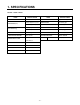
1. SPECIFICATIONS Ref. No.: 19Cuft / 22Cuft ITEMS DOOR DESIGN SPECIFICATIONS ITEMS SPECIFICATIONS Slide Rounded VEGETABLE TRAY Opaque Drawer Type 755 X 806 X 1664 (W X D X H) - 19 Cu.ft COMPRESSOR PTC Starting Type 831 X 806 X 1715 (W X D X H) - 22 Cu.ft EVAPORATOR Fin Tube Type 91 (19 cu.ft) CONDENSER Wire Condenser 101 (22 cu.
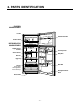
2. PARTS IDENTIFICATION FREEZER COMPARTMENT Ice Bin Freezer Door Bin Freezer Shelf REFRIGERATOR COMPARTMENT Digital Sensor Control Can Dispenser Snack Corner Dairy Bin Shelves Egg Tray Door Bin Crisper Keeps fruits and vegetables fresh and crisp.
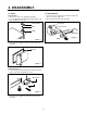
3. DISASSEMBLY 3-1 DOOR 3-2 DOOR SWITCH ● Freezer 1. To remove the door switch, pry it out with a slotted-type driver, as shown in (Figure 4). 2. Disconnect the lead wire from the switch. Door 1. Remove the hinge cover by pulling it upwards. 2. Loosen hexagonal bolts attaching the upper hinge to the body and lift the freezer door. HINGE COVER LEAD WIRE BOLT DOOR SWITCH HINGE Figure 4 Figure 1 3. Pull out the door gasket to remove from the door foam assembly.
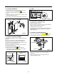
3-3 FAN AND FAN MOTOR 3-5 LAMP 1. Remove the freezer shelf. (If your refrigerator has an icemaker, remove the icemaker first) 2. Remove the grille by pulling it out and by loosening a screw. 3. Remove the Fan Motor assembly by loosening 4 screws and disassemble the shroud. 4. Pull out the fan and separate the Fan Motor and Bracket. Figure 8 FAN MOTOR SHROUD 3-5-1 Refrigerator Compartment Lamp 1. Unplug the power cord from the outlet. 2. Remove refrigerator shelves. 3.
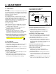
4. ADJUSTMENT 4-2-3 PTC-Applied Circuit Diagram Method for the Motor 4-1 COMPRESSOR ● Starting 4-1-1 Role The compressor intakes low temperature and low pressure gas from the evaporator of the refrigerator and compresses this gas to high-temperature and high-pressure gas. It then delivers the gas to the condenser. OVERLOAD PROTECTOR N 4-1-2 Composition The compressor includes overload protection. The PTC starter and OLP (overload protector) are attached to the outside of the compressor.
4-3 OLP (OVERLOAD PROTECTOR) 4-4 TO REMOVE THE COVER PTC 4-3-1 Definition of OLP (1) OLP (OVERLOAD PROTECTOR) is attached to the Compressor and protects the Motor by opening the circuit to the Motor if the temperature rises and activating the bimetal spring in the OLP. (2) When high current flows to the Compressor motor, the Bimetal works by heating the heater inside the OLP, and the OLP protects the Motor by cutting off the current flowing to the Compressor Motor.
5.
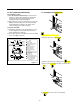
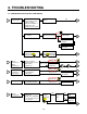
6. TROUBLESHOOTING 6-1 COMPRESSOR AND ELECTRIC COMPONENTS 1 Power Source. Remove PTC-Starter from Compressor and measure voltage between Terminal C of Compressor and Terminals 5 or 6 of PTC. (Reated Voltage ±10%)? No Voltage. OLP disconnected? YES 2 YES Replace OLP. 5 Check connection condition. Reconnect. Applied voltage isn't in range of Rating Voltage ±10%. Check resistance of Motor Compressor. Check resistance between M-C, S-C and M-S in Motor Compressor.
6-2 PTC AND OLP Separate PTC-Starter from Compressor and measure resistance between No. 5 and 6 of PTC-Starter with a Tester.(Figure 12) Observation value is 115V/60Hz : 6.8Ω±30% Check another electric component. The resistance value is 0Ω (short) or ∞ (open). Replace PTCStarter Shows continuity Separate OLP from Compressor and check resistance value between two terminals Open of OLP with a Tester. (Figure 13) Check another electric component. Replace OLP.
6-3 OTHER ELECTRIC COMPONENTS ▼ Not cooling at all Compressor doesn't run. Check for open short or incorrect resistance readings in the following components Cause a. Starting devices Short, open or broken. b. OLP Poor contact or shorted. c. Compressor coil Coil open or shorted. d. Wiring harness Poor contact or shorted. Replace indicated component. ▼ Poor cooling performance Compressor runs poorly. Fan motor doesn't run. Check a starting voltage. Low voltage. Raise voltage.
6-4 SERVICE DIAGNOSIS CHART COMPLAINT POINTS TO BE CHECKED REMEDY No Cooling. • Is the power cord unplugged from the outlet? • Check if the power Switch is set to OFF. • Check if the fuse of the power Switch is shorted. • Measure the voltage of the power outlet. • Plug into the outlet. • Set the switch to ON. • Replace the fuse. • If the voltage is low, correct the wiring. Cools poorly. • Check if the unit is placed too close to the wall.
6-5 REFRIGERATING CYCLE ▼ Troubleshooting Chart STATE OF THE UNIT CAUSE STATE OF THE EVAPORATOR TEMPERATURE OF THE COMPRESSOR REMARKS LEAKAGE RESTRICTED BY DUST PARTIAL LEAKAGE Freezer compartment and Refrigerator don't cool normally. Low flowing sound of Refrigerant is heard and frost forms in inlet only. A little higher than ambient temperature. • Refrigerant level is low due • to a leak. • Normal cooling is possible by • restoring the normal amount of • refrigerant and repairing the leak.
▼ General Control of Refrigerating Cycle NO. ITEMS UNIT 1 Pipe and piping system opening time Min. Pipe: within 1 hour. Comp: within 10 minutes. Drier: within 20 minutes. To protect moisture penetration. The opening time should be reduced to a half of the standards during rain and rainy seasons (the penetration of water into the pipe is dangerous). 2 Welding Nitrogen pressure Weld under Nitrogen atmosphere. (N2 pressure: 0.1~0.2 kg/cm2) To protect oxide scale formation.
7. DESCRIPTION OF FUNCTION & CIRCUIT OF MICOM 7-1 FUNCTION 7-1-1 Function 1. When the appliance is plugged in, it is set to "3" for the Refrigerator. You can adjust the Refrigerator control temperature by pressing the ADJUST button. 2. When the power is initially applied or restored after a power failure, it is automatically reset to "3". 1 2 3 4 WARMER 5 COLDER TEMPERATURE ADJUST 7-1-2 Defrost Cycle 1.
7-1-4 Defect Diagnosis Function 1. Defect diagnosis functions are easy SVC when defects occur which can affect product performance. 2. When a defect occurs, the buttons will not operate; but the tones. such as "ding". will sound. 3. When the defect CODE removes the sign, it returns to normal operation (RESET). 4. The defect CODE shows on the refrigerator DISPLAY as temperature LED, and the other LED turns off.
7-1-5 TEST Mode 1. The Test mode allows checking the PCB and the function of the product as well as finding out the Defective part in case of an error. 2. The test button is on the main PCB of the refrigerator (Test S/W). The test mode will be cleared in 2 hours regardless of the type of test mode. 3. While in the test mode, the ADJUST button will not operate. 4. After exiting the test mode, be sure to reset by unplugging and then plugging in the appliance. 5.
7-2 PCB FUNCTION 7-2-1 Power Circuit 1. Power is supplied to the control board at pins 1 and 5 of connector #4.
7-2-2 Load / Buzzer Drive & Open Door Detection Circuit 1.
2.
7-2-3 Temperature Sensor Circuit Voltage supplied to each sensor wil range between 0.5 volts -22°F(-30°C) and 4.5 volts 122°F(50°C) depending upon the temperature in the compartments. A measurement of 0 volts indicates a short in the sensor circuit. A measurement of 5 volts indicates an open in the sensor circuit.
7-3 RESISTANCE SPECIFICATION OF SENSOR TEMPERATURE RESISTANCE OF FREEZER SENSOR RESISTANCE OF REFRIGERATOR & DEFROST SENSOR - 20 ˚C (-4 °F) 22.3 KΩ 77 KΩ - 15 ˚C (5 °F) 16.9 KΩ 60 KΩ - 10 ˚C (14 °F) 13.0 KΩ 47.3 KΩ - 5 ˚C (23 °F) 10.1 KΩ 38.4 KΩ 0 ˚C (32 °F) 7.8 KΩ 30 KΩ + 5 ˚C (41 °F) 6.2 KΩ 24.1 KΩ + 10 ˚C (50 °F) 4.9 KΩ 19.5 KΩ + 15 ˚C (59 °F) 3.9 KΩ 15.9 KΩ + 20 ˚C (68 °F) 3.1 KΩ 13 KΩ + 25 ˚C (77 °F) 2.5 KΩ 11 KΩ + 30 ˚C (86 °F) 2.0 KΩ 8.9 KΩ + 40 ˚C (104 °F) 1.
7-4 TROUBLESHOOTING COMPLAINT SOLUTION 1. Check supply voltage to refrigerator POSSIBLE CAUSES 1. Supply voltage not within specifications 2. Check wiring and connectors to PWB board SYMPTOM 2. Open in wiring harness from PWB board 3. Check door monitor circuit 1. No Display at all not operating 3. Open in door monitor switch circuit 1. Check supply voltage to refrigerator Electronic Display correctly 1. Supply voltage not within specifications 2. Partial or 1.
7-5 MAIN PWB ASSEMBLY AND PARTS LIST 7-5-1 Main PWB Assembly - 25 -
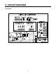
8. EXPLODED VIEW & REPLACEMENT PARTS LIST CASE PARTS CAUTION: Use the part number to order part, not the position number.
FREEZER PARTS CAUTION: Use the part number to order part, not the position number.
REFRIGERATOR PARTS CAUTION: Use the part number to order part, not the position number.
DOOR PARTS CAUTION: Use the part number to order part, not the position number.
P/No. 3828JL8015A MAR.