
Product Manual
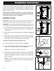

Mounting the control panel
1. Determine mounting location for panel. If
distance exceeds the length of either the fl oat
switch cables or the pump power cables,
splicing will be required. For outdoor or wet
installation, we recommend the use of a SJE-
Rhombus
®
liquid-tight junction box with liquid-
tight connectors to make required connections.
You must use conduit sealant to prevent
moisture or gases from entering the panel.
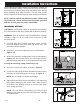
2. Mount control panel with mounting fl anges
furnished with control panel.
3. Determine conduit entrance locations on control
panel. Check local codes and schematic for
the number of power circuits required.
NOTE: Be sure the incoming power, voltage,
amperage, and phase meet the requirements
of the pump motors being installed. If in doubt,
see the pump identifi cation plate for electrical
requirements.
4. Drill proper size holes for type of connectors
being used.
NOTE: If using conduit, be sure that it is of
adequate size to pull the pump and switch
cables through. You must use conduit
sealant to prevent moisture or gases from
entering the panel.
5. Attach cable connectors and/or conduit
connectors to control panel.
FOR INSTALLATION REQUIRING A SPLICE,
FOLLOW STEPS 6-10;
FOR INSTALLATION WITHOUT A SPLICE,
GO TO STEP 11.
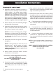
6. Determine location for mounting junction box
according to local code requirements. Do not
mount the junction box inside the sump or
basin.
7. Mount junction box to proper support.
Installation Instructions
8. Run conduit to junction box. Drill proper size
holes for the type of conduit used. Attach liquid-
tight connectors to junction box.
9. Identify and label each wire before pulling
through conduit into control panel and junction
box. Pull pump power cables and control switch
cables through connectors into junction box.
Make wire splice connections at junction box.
10. Firmly tighten and seal all fi ttings on junction
box. Insure all cable connectors are liquid-tight
and sealed.
11. If a junction box is not required, connect
pump and fl oat wires to proper position on
terminals. See schematic inside control panel
for terminal layouts.
12. Connect control/alarm and pump power
conductors to proper position on terminals.
See schematic inside control panel for terminal
connections.
NOTE: It is the recommendation of the factory to
use separate pump and control/alarm power
sources.
VERIFY CORRECT OPERATION OF CONTROL
PANEL AFTER INSTALLATION
IS COMPLETE.
7249000B
- 3 -