
Product Manual
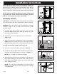
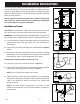

Mounting the Control Panel
1. Determine mounting location for panel. If dis-
tance exceeds the length of either the fl oat
switch cables or the pump power cables,
splicing will be required. For outdoor or wet
installation, we recommend the use of an SJE-
Rhombus
®
liquid-tight junction box with liquid-
tight connectors to make required connections.
You must use conduit sealant to prevent
moisture or gases from entering the panel.
2. Mount control panel with mounting devices
furnished.
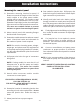
3. Determine conduit entrance locations on control
panel.
NOTE: Be sure the incoming power, voltage,
amperage, and phase meet the requirements
of the pump motors being installed. If in doubt,
see the pump identifi cation plate for electrical
requirements.
4. Drill proper size holes for type of connectors
being used.
NOTE: If using conduit, be sure that it is of ad-
equate size to pull the pump and switch cables
through.
5. Attach cable connectors and/or conduit con-
nectors to control panel.
FOR INSTALLATION WITHOUT A SPLICE,
GO TO STEP 10; FOR INSTALLATION RE-
QUIRING
A SPLICE, FOLLOW STEPS 6-9.
6. Determine location for mounting junction box
according to state and local code requirements.
Mount the junction box to proper support.
7. Run conduit to junction box. Drill proper size
holes for the type of conduit used. Attach con-
nectors to junction box.
Installation InstructionsInstallation InstructionsInstallation InstructionsInstallation InstructionsInstallation InstructionsInstallation InstructionsInstallation InstructionsInstallation InstructionsInstallation Instructions
8. Identify and label each wire before pulling
through conduit into control panel and junction
box. Make wire splice connections at junction
box.
9. Firmly tighten all fi ttings on junction box.
10. If a junction box is not required, pull cables
through conduit into control panel.
11. Set motor protective switches:
a) set the dials to match motor full load
amps.
b) turn dial on motor protective switch to the
ON position.
NOTE: Resetting the dial with power applied
to the motor protective switch could start
the motor.
12. Connect pump wires directly to the motor con-
tactors terminal positions T1, T2, and T3.
NOTE: Three-phase motors will run in either
direction. Check pump motor before installation
for proper rotation. To correct rotation, change
pump cable connections on any two terminals
T1-T2-T3.
13. Connect “power-in” conductors to proper
locations: 208/240/480 VAC on the 3 position
terminal block. Install tagged factory wire to
appropriate transformer primary voltage tap.
VERIFY CORRECT OPERATION
OF CONTROL PANEL AFTER
INSTALLATION IS COMPLETE.
- 3 -
7228000B