
Installation Sheet


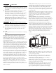


Table Of Contents

5755000K Copyright © Liberty Pumps, Inc. 2020
All rights reserved. 7 | EN
Gravity Fall: The unit accepts wastewater by gravity; it does not
vacuum in water. All inlet pipework must have a positive gravity
fall (1/4 inch per foot drop minimum).
Vertical Lift: If vertical lift is required, this must precede the
horizontal pipe run. All vertical lifts should rise as close to the
macerator as possible, allowing only for the need to clear the
toilet tank. The initial horizontal run should not exceed 12 inches.
Once the horizontal run is started, do not change directions in a
vertical manner.
Discharge: All discharge piping from the unit should run either
directly vertical or in a horizontal plane (with a minimum 1/4 inch
per foot drop) to the point of discharge. Pipework must not be
installed with a diagonal upward slope from the unit to the point
of discharge. Long downward pitched runs of discharge piping, or
piping where the point of discharge is at a lower elevation than
the macerator unit, should be designed to prevent siphoning from
the macerator tank.
Friction: Friction losses from horizontal runs without 1/4 inch per
foot pitch will reduce the amount of vertical lift the system is
capable of handling. Refer to Figure 3. Consult factory for proper
sizing if there are long runs or multiple elbows.
Lift Calculations: To pump vertically and horizontally, calculate
3 ft of vertical lift as equivalent to 30 ft of horizontal run. Each
bend or change of direction gives a pressure drop, which must be
calculated into the total head of the unit. As an estimate, reduce
discharge height by 3 ft for each 90° bend.
For example: 1” Schedule 40
PVC pipe is used for the
discharge and runs
horizontally for 1 ft, then
turns 90°, and rises 5 ft
vertical. Then it travels
horizontal with another 90°
turn (3 turns in total) and
connects with the soil-stack.
Refer to Figure 2.
Calculations:
[A] Total vertical lift 5 ft= 5 ft
vertical
[C+D+E] Total horizontal run
43 ft = 4.3 ft vertical
[B] Total of three 90° elbows
= 9 ft vertical
Add the three calculation
totals together to get 18.3 ft
of vertical head (lift). Referring
to Figure 3, the application
would result in a flow rate of
23 gal/min (60 Hz).
Figure 2. Example Calculations
Figure 3. Performance Curve
Macerating Unit Preparation
Auxiliary inlets should be plumbed using the supplied auxiliary
inlet couplings and/or reducing bushing when connecting to
either 2” or 1-1/2” standard Schedule 40 PVC pipe. A plug must be
removed by turning until the rib is vertical and pulling outward.
Pliers may be required if unit has been stored.
Both the discharge and vent flanges are shipped from the factory
in the horizontal orientation. If the installation allows for a vertical
orientation, the four screws must be removed from each in order
to flip the flange. The decorative cover will need to be modified
with the use of a hole saw and cutters to remove material. A
template is provided on the underside of the decorative cover.
1 ft
[30.5cm]
5 ft
[1.5m]
30 ft
[9.1m]
12 ft
[3.7m]
[E]
[B]
[B]
[B]
[D]
[A]
[C]
0 5 10 15 20 25 30 35 40 45
0
5
10
15
20
25
30
35
40
0
1.5
3.0
4.6
6.1
7.6
9.1
10.7
12.2
37.9 56.818.90 75.7 94.6 113.6 132.5 151.4 170.3
US Gallons Per Minute
Total Head in Feet
Liters Per Minute
Total Head in Meters
50 Hz
60 Hz
Discharge flange
PVC solvent
weld
1” schedule
40 PVC pipe
Vent flange
PVC
solvent weld
1-1/2” schedule
40 PVC pipe
Discharge and vent
flanges
in horizontal orientation
Discharge and vent flanges
in vertical
orientation