
Manual

7. Mount junction box to proper support.
8. Run conduit to junction box. Drill proper size holes for the type of conduit used.
9. Identify and label each wire before pulling through conduit into control panel and junction box. Make wire
splice connections at junction box.
10. Firmly tighten all fi ttings on junction box.
11. Set motor protective switches:
a) set the dials to match motor full load amps.
b) turn dial on motor protective switch to the ON position.
NOTE: Resetting the dial with power applied to the motor protective switch could start the motor.
12. If a junction box is not required, pull cables through conduit into control panel.
13. Connect pump wires per wiring diagram or schematic, and sensor or fl oat wires to the proper terminals as
shown on the schematic.
14. Connect pump, control, and alarm incoming power conductors to proper position on terminals. See schematic
for terminal connections.
VERIFY CORRECT OPERATION OF CONTROL PANEL AFTER INSTALLATION IS COMPLETE.
Installation of Level Sensor and Floats
CAUTION: If control switch cables are not wired and mounted in the correct order, the pump system will not
function properly. Sensor and fl oat cables need to run in separate conduit from pump and power lines.
WARNING: Turn off all power before installing pump wires in pump chamber. Failure to do so could result in
serious or fatal electrical shock.
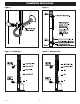
NOTE: The Level Sensor operates between 0 and 39.9 inches of water pressure. The Level Sensor reads 0 inches
at the approximate point shown in Figure 2. As the liquid level rises, the IFS display shows depth of liquid from the
zero point. The minimum set point for the stop or redundant off level is 3 inches (measured from 0) see Figure 2.
The maximum set point allowed is 39.9 inches (measured from 0). Operating temperature range is 32ºF (0ºC)
to 120ºF (50ºC).
1. Determine the nominal operating levels for the confi guration, as illustrated in Figure 3 or 4.
2. Position Level Sensor at appropriate location on pipe and secure sensor and vent as shown in Figure 2 using
hose clamps.
WARNING: Do not support the Level sensor by the cable. Position the sensor in the tank so that nothing is
pushing in the diaphragm.
3. Position vent so it is above the water level and stow excess vent tube as shown in Figure 2.
WARNING: Do NOT kink or place black tubing under hose clamp. Doing so will cause sensor to fail.
4. If optional high water or redundant off fl oats are used, position and secure as shown in Figures 1, 3 or 4.
Redundant off fl oat should be located to activate at approximately the zero point for the Level Sensor per
Figure 3 or 4.
NOTE: Liberty Pumps, Inc. recommends using the optional high water alarm fl oat for added protection against
fl ooding.
5. Tighten all hose clamps using a screw driver. Over tightening may result in damage to the plastic parts.
NOTE: All hose clamp components are made of 18-8 stainless steel material. See your Liberty Pumps, Inc.
supplier for replacement parts.
6. Functionally test the system by fi lling the tank and witnessing proper operation.
Installation Instructions
-2-
7281000A