HEAT REMOVAL /ENVIRONMENTAL CONTROL Drycoolers - 60 Hz GENERAL DATA
TABLE OF CONTENTS LIEBERT DRYCOOLERS . . . . . . . . . . . . . . . . . . . . . . . . . . . . . . . . . . . . . . . . . . . . . . . . . . . . . . . . .1 FEATURES AND BENEFITS OF LIEBERT DRYCOOLERS . . . . . . . . . . . . . . . . . . . . . . . . . . . . . . . . . . .2 SELECTION PROCEDURE . . . . . . . . . . . . . . . . . . . . . . . . . . . . . . . . . . . . . . . . . . . . . . . . . . . . . . . .3 PERFORMANCE DATA . . . . . . . . . . . . . . . . . . . . . . . . . . . . . . . . . . . . . . . . . . . . . . . .
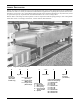
Figures Figure 1 Figure 2 Figure 3 Figure 4 Figure 5 Figure 6 Figure 7 Figure 8 Figure 9 Figure 10 Figure 11 Drycooler model numbers . . . . . . . . . . . . . . . . . . . . . . . . . . . . . . . . . . . . . . . . . . . . . . . . . . . . . . . . . . 1 Capacity correction factor. . . . . . . . . . . . . . . . . . . . . . . . . . . . . . . . . . . . . . . . . . . . . . . . . . . . . . . . . . 5 Pressure drop correction factor . . . . . . . . . . . . . . . . . . . . . . . . . . . . . . . . . . . . . . . . . .
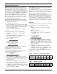
LIEBERT DRYCOOLERS Liebert drycoolers are designed to be used in conjunction with water cooled refrigeration and air conditioning machines as well as a variety of commercial and industrial applications requiring the rejection of heat from machinery or processes via a cooling fluid. During periods of low ambient temperatures, drycoolers may assist or replace the capacity requirements of mechanical chillers for a “free cooling” effect.
FEATURES AND BENEFITS OF LIEBERT DRYCOOLERS Heat Rejection Module The low-profile direct-drive propeller-fan type drycoolers utilize optimum circuitry to balance the heat rejection of the corresponding load. Constructed of aluminum with a copper-tube aluminum coil, the unit is quiet and corrosion resistant. Low Noise Level All Liebert drycoolers are designed to operate at a minimal noise level.
SELECTION PROCEDURE The MBH found should be equal to or greater than the “required MBH /ITD.” If the MBH is less than required, repeat from Step 2 with a larger model. You may wish to repeat from Step 2 with a smaller model for the most economical selection meeting the required MBH/ITD. Pressure Drop - After selecting a model, look up the unit pressure drop following Step 3 and 4 above. Multiply the pressure drop found by the Figure 3 correction factor.
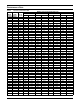
PERFORMANCE DATA Table 4 Drycooler performance data Model GPM Number Range Standard Models 033 6-12 069 6-12 12-24 092 9-18 18-36 24-48 109 12-24 24-48 112 24-48 39-78 139 12-24 24-48 174 24-48 36-72 197 24-48 48-96 225 24-48 39-78 260 24-48 36-72 310 24-48 48-96 350 24-48 48-96 72-144 352 24-48 36-72 419 24-48 48-96 466 39-78 60-120 491 24-48 48-96 72-144 620 48-96 96-192 650 60-120 78-156 120-240 700 48-96 96-192 144-288 790 48-96 96-192 880 78-156 120-240 940 48-96 96-192 144-288 MBH/°F Initial Temper
Table 4 Drycooler performance data (continued) Model GPM Number Range Quiet-Line Models 040 6-12 12-24 057 18-36 24-48 060 12-24 24-48 080 12-24 24-48 111 24-48 36-72 121 24-48 48-96 158 24-48 36-72 173 24-48 48-96 178 24-48 48-96 72-144 205 24-48 36-72 248 24-48 48-96 347 48-96 96-192 356 48-96 96-192 144-288 453 48-96 96-192 498 48-96 96-192 144-288 MBH/°F Initial Temperature Difference 1.5 GPM/CIR 2.0 GPM/CIR 2.5 GPM/CIR 3.0 GPM/CIR No. of Circuits MBH/ITD PD ft. water MBH/ITD PD ft.
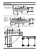
DIMENSIONAL DATA Figure 4 Dimensional data—1-4 fan models L 43-9/16" (962mm) 70" (1778mm) Eyebolts for lifting condenser provided on 4, 6 & 8 fan models only 37-7/8" (962mm) Height to top of fan guard 43-1/8" (1095mm) 18" (457mm) C 43-3/16" (1097mm) Figure 5 Center leg provided on 4 & 8 fan models only Dimensional data—6 & 8 fan models L 36" (914.
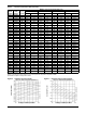
Table 5 Drycooler physical data Drycooler Model Standard Models -033 -069 -092 -109 -112 -139 -174 -197 -225 -260 -310 -350 -352 -419 -466 -491 -620 -620 -650 -650 -650 -700 -700 -700 -790 -790 -880 -880 -940 -940 -940 Quiet-Line Models -040 -057 -060 -080 -111 -121 -158 -173 -178 -205 -248 -347 -356 -356 -453 -453 -498 -498 -498 Circuits A B C L #Fans & Motors** Conn FNPT In/Out any any any any any any any any any any any any any any any any 641 32 80 521 40 96 641 32 641 32 801 52 961 64 32 42
ELECTRICAL DATA Table 6 Drycooler electrical data # of Fans 1 Model # 33,69,92,109,112 2 3 4 6 8 139,174,197,225 260,310,350 352,419,466,491 620,650,700 790,880,940 Pump Hp ph FLA WSA OPD ph FLA WSA OPD ph FLA WSA OPD ph FLA WSA OPD ph FLA WSA OPD ph FLA WSA OPD 208/230/60 0.75 1 11.6 13.5 20.0 - 0.75 3 15.0 3 10.5 11.4 15.0 3 14.0 14.9 15.0 3 17.5 18.4 20.0 3 24.5 25.4 25.0 3 31.5 32.4 35.0 1.5 3 10.1 11.8 15.0 3 13.6 15.3 20.0 3 17.1 18.8 25.0 3 20.6 22.3 25.0 3 27.6 29.
Table 7 Drycooler electrical data—Quietline models # of Fans 1 2 3 4 6 8 Model # 40,57,60 80,111,121 158,173,178 205,248 347,356 453,498 Pump Hp ph FLA WSA OPD ph FLA WSA OPD ph FLA WSA OPD ph FLA WSA OPD ph FLA WSA OPD ph FLA WSA OPD 208/230/60 0.75 3 5.3 6.2 1.5 3 8.4 10.1 15.0 2.0 3 9.3 11.2 15.0 3 11.1 13.0 20.0 3 12.9 14.8 20.0 3 14.7 16.6 20.0 3 18.3 20.2 25.0 3 21.9 23.8 30.0 3.0 3 12.4 15.1 25.0 3 14.2 16.9 25.0 3 16.0 18.7 25.0 3 17.8 20.5 30.0 3 21.4 24.1 30.
GUIDE SPECIFICATIONS Standard Features for Direct Drive Propeller Fan Drycoolers Furnish and install Liebert Model ________ Air-Cooled Drycoolers, arranged for vertical air flow. Drycoolers shall be draw-through design and shall perform in accordance with the schedule. General Each drycooler shall consist of casing, drycooler coil, propeller fans direct-driven by individual fan motors, fan guards, and mounting legs. Fan motors shall be furnished for operation on a _______ V, ____PH, ______ Hz power supply.
COMPONENT ASSEMBLY/INSTALLATION Leg Assembly The legs are shipped loose and are to be field mounted as shown with the hardware provided. Secure each leg to drycooler frame at all four points shown using hardware provided Outlet Electrical service supply by others Inlet Models 069-491 Models 620 through 940 have 2 sets of connections on end of unit Figure 7 General arrangement diagram Fill* Typical rigging Rigging Holes in the drycooler legs permit lifting the unit. Spreader bars are required.
APPLICATION/INSTALLATION GUIDELINES Location Guidelines To ensure an adequate air supply, locate drycoolers in a clean air area, away from loose dirt and foreign matter that may clog the coil. In addition, drycoolers must not be placed near steam, hot air, or fume exhausts. Also, drycoolers should be no closer than 3 feet from a wall, obstruction or adjacent unit with no obstructions over the unit. Install drycoolers in a level position to assure proper vent and drain.
PUMP PACKAGES & EXPANSION TANK - OPTIONS Figure 8 Pump package See Note 1 Figure 10 Expansion tank 30-1/4" (768.4mm) Pump discharge connections 19" (483mm) Pump suction connections Provided on dual pump package only Expansion Tank- (P/N 1C16717P1) Figure 9 Pump mounting 1/2" (12.7mm) diameter holes This tank, included in a standard pump package, has an internal volume of 8.8 gal. (33 l) and a maximum pressure of 100 psi (690 kPa).
SUPPLEMENTARY APPLICATION DATA Table 9 Room dew point temperatures Table 11 Dry bulb °F (°C) Wet bulb °F (°C) Rel. hum. % Dew point* °F (°C) 70 57.2 45 41.1 70 58.5 50 50.5 72 58.9 45 72 60.0 75 75 Type “L” copper tube Diameter (in.) Inside Gal/ft (L/m) 50.0 .50 0.430 0.0075 (0.09) 50 52.4 .625 0.545 0.0121 (0.15) 61.2 45 52.4 .75 0.666 0.0181 (0.22) 62.5 50 55.0 .875 0.785 0.0251 (0.31) 1.125 1.025 0.0429 (0.53) 1.375 1.265 0.0653 (0.81) 1.625 1.
HEAT REMOVAL /ENVIRONMENTAL CONTROL Drycoolers - 60 Hz GENERAL DATA The Company Behind the Products Technical Support With over a million installations around the globe, Liebert is the world leader in computer protection systems. Since its founding in 1965, Liebert has developed a complete range of support and protection systems for sensitive electronics: United States 1050 Dearborn Drive P.O.