GXT2 - 3X1 Intelligent, High Frequency, Online UPS 10/15/20kVA USER MANUAL E1-20010329-C-1.
IMPORTANT INSTRUCTIONS FOR SAFE USE The UPS must be commissioned by a Liebert - approved engineer before it is put into service. Failure to observe this condition will invalidate any implied warranty . Do not apply power to this equipment before it has been commissioned by a Liebert - approved engineer. He will validate the installation work and install ' site information ' into the micro-controller memory. This information is required to substantiate any warranty claims that might be made.
Do not place magnetic storage media on top of the unit as it can corrupt the data stored on them. Electromagnetic Compatibility WARNING This is a Class A UPS product. In a domestic environment this product may cause radio interference, in which case the user may be required to take additional measures. Limits on use: WARNING This UPS should not be supplied from electrical power systems of the 'IT' (Impedance a Terre ) type.
Content Chapter 1 Introduction 1.1 Application 1.3 System Function Block 1.4 Features Chapter 2 Installation 2.1 Unpacking Inspection 2.2 Outline and Panel Description 2.2.1 Outline 2.2.2 Front Panel 2.2.3 Rear Panel 2.3 Installation 2.3.1 Important Note 2.3.2 Installation Procedure 2.4 Connection of External Batteries Chapter 3 Operation 3.1 Operating Mode 3.1.1 Normal Mode 3.1.2 Bypass Mode 3.1.3 Battery Mode 3.1.4 ECO Mode 3.1.5 Failure Mode 3.2 Operation 3.2.1 Startup and Initialization 3.2.
3.2.6 LCD Panel Operation Chapter 4 Maintenance and Storage I. Battery Maintenance II. Keep Air Vent Unblocked III. UPS State Check IV. Function Inspection Chapter 5 Troubleshooting Appendix 1 LCD Panel Displays and Operation 1. Constitution of Display Panel 2. Function of display Panel 3. Menu Operation 4.
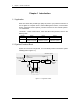
Chapter 1 Product Introduction Chapter 1 Introduction 1.1 Application GXT2-3X1 Series UPS provides high quality AC power to your precision instrument. It can be applied in Computer Center , Network Management Center, Communication System, Automation Control System, precision instrument or other Critical Systems. 1.
Chapter 1 Product Introduction 7 Maintenance bypass Backup UPS bypass bypass Breaker Utility Rectifier Electronic Transfer Switch Inverter Utility Breaker Load Maintenance switch Charger Master UPS Battery Group1 Battery Group 2 Figure 1-2 hot-standby system 1.4 Features GXT2-3X1 Series Three phase input/Single phase output 10kVA/15kVA /20kVA UPS is an advanced, intelligent, Online with Sinusoidal waveform output UPS system.
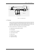
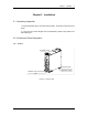
Chapter 2 Installation 9 Chapter 2 Installation 2.1 Unpacking Inspection 1. Unpack the packing box to move the UPS to position , be careful not to drop it as it is heavy. 2. In the event of product damage due to transportation, please notify Liebert or its authorized agent. 2.2 Outline and Panel Description 2.2.1 Outline LCD Display Panel Supporting caster Adjustable Footpad Ventilation holes on front panel Figure 2-1 UPS Front view E1-20010329-C-1.
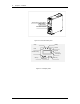
Chapter 2 Installation Air-inlet holes on Front Panel Utility Switch Bypass Switch Maintenance Switch Figure 2-2 Front view without panel Utility Battery Inverter Fault Bypass On/Silence Key LCD Display Off Key Scroll Key Figure 2-3 LCD display Panel E1-20010329-C-1.
Chapter 2 Installation contact closure port Alarm Relay Port Ventilation holes Input/Output Terminals block Figure 2-4 rear panel 2.2.2 Front Panel Parts' Function Description Input Switch Used for controlling the utility input to UPS.
Chapter 2 Installation It can be included in monitoring system defined by users . Heat Dissipation and ventilation holes Used for heat dissipation and ventilation of UPS 2.3 Installation 2.3.1 Important Note 1. Please position the UPS on the flat ground/surface .. 2.
Chapter 2 Installation Input hot line U V W Input neutral line 13 output hot line U P S output neutral line Load N/E Figure 2-5 (b) wrong cable connection Warning Classified according to European standard EN55022 , this is an A level UPS product. When it is used in family house, it may generate radio interference, user should take other measures in this condition. 2.3.2 Installation Procedure 1.
Chapter 2 Installation + - + - L1 B_L Battery 1¡ + °¡ ± Terminal Battery1 + Terminal Battery 1¡- °-Terminal ¡ ± Terminal Battrery1 B_N Hot standby B_N End Hot standby B_L End Hot standby L1 End Battery 2¡ °+¡ ± Terminal Battery2 + Terminal Battery 2¡ -°¡ T ±erminal Battery2 - Terminal Figure 2-6(a) 10kVA Input/output terminals( upper terminals' block) N U L W V N Input GND Output GND Output Neutral line Input Neutral line Input U phase line Output phase line Input V phase line Inp
Chapter 2 Installation 15 Figure 2-6(d) 15/20kVA Input/output terminals( lower terminals' block) Note For 10kVA system, at least 8AWG or 10mm2 copper wire should be used for input neutral line, input U phase line, hot standby L1 terminal, B_L terminal, B_N terminal and output neutral line and hot line;input V or W phase lines and battery lines should be 10AWG or 6mm2 copper wire at least.
Chapter 2 Installation Battery Cabinet Breaker of Battery Cabinet Battery 2 Battery 1 + _ + _ Figure 2-10 connection of external batteries 5. Turn the switch on the battery cabinet to " ON " position. Note The battery connection and replacement should be done when the UPS is Completely switched OFF, if batteries are replaced while UPS is ON (hot - swappable ) pay attention not to reverse battery polarity. 2.5 Wire Connection for Hot Standby UPS 1.
Chapter 2 Installation Backup UPS + - L1 B_L B_N + - + - L1 B_L L N Output phase line - Output Neutral line + Master UPS B_N Output neutral line of Backup UPS is connected to the N terminal of Master's bypass Output phase line of Backup UPS is connected to the L terminal of Master's bypass N U V W L N N U V W Output GND in Parallel Input GND in Parallel Input Neutral line in Parallel Input U phese line in Parallel Input V phase line in Parallel Input W phase line in parallel
Chapter 2 Installation Backup UPS + - + - Master UPS L1 B_L B_N + - + - L1 B_L B_N Output neutral line of Backup UPS is connected to the N terminal of Master's bypass Output phase line of Backup UPS is connected to the L terminal of Master's bypass V W L N N U V W L N Output Neutral line U Output phase line N Output GND in Parallel Input GND in Parallel Input Neutral line in Parallel Input U phese line in Parallel Input V phase line in Parallel Input W phase line in paral
Chapter 3 Operation 19 Chapter 3 Operation 3.1 Operating Mode 3.1.1 Normal Mode When the input Utility voltage and the load are within specifications, the load is supplied by inverter, which draws power from rectifier; meanwhile, the charger float-charges or equalize-charges the battery. When in Normal mode, the Utility indicator and inverter indicator on the LCD panel be green in colour ,as shown in Fig. 3-1. OUTPUT VOLT 220.
Chapter 3 Operation OUTPUT VOLT 215.0V Figure 3-2 Note Under this mode, if the bypass power fails or bypass voltage exceed the bypass voltage windows. , the UPS will not provide power to the load. 3.1.3 Battery Mode When the UPS is in Normal mode, in the event of Utility failure or Utility voltage outside tolerances, the rectifier and charger will turn off , the battery begins to discharge and supply the load through inverter.
Chapter 3 Operation 21 Although the battery had been fully charged at factory before delivery, the transport and storage may result in loss of capacity , hence charging the battery for 8 hours is required before installing the UPS , so as to ensure adequate battery backup time. 3.1.4 ECO Mode ECO mode is the economic operation mode. For the load equipment which is less critical , users can select ECO mode to power the equipment to reduce the power consuming.
Chapter 3 Operation OUTPUT VOLT 215.0V Figure 3-5 3.2 Operation 3.2.1 Startup and Initialization After checking and making sure that the input and output cables are connected correctly, turn on the Utility switch and the bypass switch (for long backup time UPS, turn on the battery switch before closing the Utility switch). Then the system starts up, the internal fan begins to run, and the system begins to conduct self-test.
Chapter 3 Operation 23 OUTPUT VOLT 220.0V Figure 3-7 Note If the previous shutdown was resulted from termination of battery discharge because of Utility failure, the automatic function will be activated when the Utility restores. 2, After the system is started up properly , apply the load gradually and monitor the load condition through LCD, as shown in Figure 3-8: LOAD 70.0% Figure 3-8 3, In the event of load exceeding the rated capacity of the UPS, of 105% load , the buzzer will beep every 0.
Chapter 3 Operation 1. Press and hold the ON/SILENCE button for about 1 second, after a beep and system self-test, the battery indicator and inverter indicator turns green, as shown in Fig. 3-9, and the buzzer beeps every 3 seconds, indicating the UPS is operating in Battery mode. OUTPUT VOLT 220.0V Figure 3-9 2. Overload process is same with the above "Start from the utility power".
Chapter 3 Operation 25 Note After battery test, the battery state information will be refreshed. In the event of battery fault due to the battery not bang fully charged is detected during test, user may re-test the battery after fully charging it to confirm that the fault is removed. 3.2.4 Turn off the Inverter 1.
Chapter 4 Maintenance and Storage 27 Chapter 4 Maintenance and Storage I. Battery Maintenance The internal battery of GXT2-3X1 series UPS is sealed, lead-acid, maintenance-free battery. The battery life depends on the ambient temperature, charge and discharge cycles . High ambient temperature and deep discharge can shorten battery life. To ensure battery life, the battery should be maintained regularly: Keep the ambient temperature between 15℃ and 25℃.
Chapter 4 Maintenance and Storage Notice 1. Never short-circuit the battery terminals, which may result in fire. 2. Never open the battery, as the electrolyte is harmful to human body. In the event of inadvertent contact of electrolyte, immediately rinse it off with water and go to hospital for treatment . II. Keep Air Vent Unblocked 1. Regularly clean the system, especially the air inlet and air outlet. Make sure the air flows freely inside the chassis. Use vacuum cleaner for cleaning when necessary.
Chapter 5 Handling Abnormal Problem 29 Chapter 5 Troubleshooting In the event of UPS fault, please check and remove the fault immediately following the methods described in the table below. If the fault persist , please contact Liebert or its authoriged agents. Sequence No. Phenomena Description 1 No panel display and system self-test when the Utility switch is in the ON position. A. Utility hasn't been introduced into the system; B. Input undervoltage.
Chapter 5 Handling Abnormal Problem Sequence No. Phenomena Description Cause Action 9 The UPS has reduced A. The battery is not battery time. fully charged; B. The battery is not able to hold a full charge due to age. A. Allow the battery to charge for more than 8 hours when the Utility is normal, and then re-test the discharge time; B. The battery needs replacement, please contact the Liebert or its authoriged agent. .
Chapter 6 Service after Sales 31 Appendix 1 LCD Panel Displays and Operation LCD display interface is formed by LCD, LED and keys (see Appendix-Figure 1-1), it mainly finish the displaying and control of the following information: UPS basic parameter information, operating parameters information, alarm information, failure code information and function setup information.
Chapter 1 Product Introduction 5)Battery indicator(green):when the battery is discharging , it is on; when it not discharging , the indicator is off. 2.
Chapter 6 Service after Sales 33 (3) equalize function settings includes: Enable Disablet No change (4) temperature Compensation settings includes: Enable Disable No change (5) Battery Capacity setup means the Ah of batteries used by UPS, for example: The battery capacity in two battery groups( each group contains 20 batteries) is all 100Ah, so the battery Capacity should be set up as 100Ah, includes: 24Ah 28Ah 38Ah 52Ah 65Ah 76Ah No change 84Ah 500Ah 400Ah 300Ah 200Ah 130Ah 100Ah (6)
Chapter 1 Product Introduction (8) The equipment address setup can directly change the 3-bit digit which forms the equipment's address, the equipment address range is 0~255. (9) Frequency tracking range settings includes: 1% 2% 4% 6% 10% No change User can select according to the power supply frequency requirement of load. 3.
Chapter 6 Service after Sales 35 Enter Enter scroll scroll Prohibit scroll cycle ( Display Present Value ) EC setup Enable Back to Main Menu Run Para Enter scroll ... scroll Present Second Alarm scroll Enter Enter ...
Chapter 1 Product Introduction B) After entering " function setup " menu , function information which can be setup can be viewed and set by pressing the scroll key ; when the screen displays " Return to main menu", press enter key to return the main menu of " operating parameters ".
Appendix 2 Communication Port Description 37 Dry Contact Communication Mode Port Definition NC Utility Fail NC GND Battery Undervolt 1 2 3 4 5 6 7 8 9 OFF GND NC NC Pin2 : When the Utility fails, this pin will change from OPEN to CLOSE, it is OPEN in normal state; Pin5 : When the battery voltage is low, this pin will change from OPEN to CLOSE, it is OPEN in normal state; Pin6 : When +5V voltage has been applied for 1 second, the UPS will shutdown; Pin4 : GND for signal; Pin7 : GND for signal; Other
Appendix 2 Communication Port Description Connection alarm Signal failure Signal Bypass mode signal battery low Signal Shutdown Signal Pin . 1/2/3 (normally open /common normally close) Pin . 4/5/6 (normally open/common /normally close) Pin . 7/8/9 (normally open/common /normally close) Pin . 10/11/12 (normally open/ common / normally close) Pin .
Appendix 3 Product Specification Appendix 2 Product Specification Capacity 10kVA 15kVA 20kVA Model GXT2-3X1 -0100L GXT2-3X1 -0150L GXT2-3X1 -0200L Input Input Mode Three-phase/four-line input rated voltage 400 Vac( line to line) voltage range 1. If the Phase to neutral voltage is in the range of 176-276Vac, the UPS can work normally with full load; 2.
Appendix 3 Product Specification Capacity 10kVA 15kVA 20kVA Model GXT2-3X1 -0100L GXT2-3X1 -0150L GXT2-3X1 -0200L Bypass Voltage 120~253Vac (non- ECO mode) Efficiency in Normal Mode (100% Linear Load) > 89% > 89% > 89% Efficiency in battery mode (100% Linear Load) > 88% > 88% > 88% interrupt Utility Failure time 0ms < 4ms Transferring between inverter and Bypass (Synchronized ) Voltage transient response At the Resistive Load from 0~100% or 100%~0, the Output dynamic voltage change
Appendix 3 Product Specification Capacity 10kVA 15kVA 20kVA Model GXT2-3X1 -0100L GXT2-3X1 -0150L GXT2-3X1 -0200L Environment Condition E1-20010329-C-1.
Appendix 4 Accessories Appendix 3 Accessories Optional Product name battery cabinet Product Model Remark UF-B0100-38 20 38Ah batteries UF-B0100-65 20 65Ah batteries UF-B0100-100 20 100Ah batteries E1-669001-20010230-C-1.