Precision Cooling For Business-Critical Continuity™ Liebert XDK™ Rack Enclosure With Integrated Water-Based Cooling User Manual–17kW
IMPORTANT SAFETY INSTRUCTIONS SAVE THESE INSTRUCTIONS Liebert engineers will provide comprehensive support on how to install the XDK. Extensive material, function and quality checks ensure that you fully benefit from product functions and a long service life. Nevertheless, this product can produce hazards if it is used incorrectly by untrained personnel or is not used for the correct purpose. Read these operating instructions carefully before commissioning the XDK.
TABLE OF CONTENTS IMPORTANT SAFETY INSTRUCTIONS . . . . . . . . . . . . . . . . . . . . . . . . . . . . . . . . INSIDE FRONT COVER 1.0 INTRODUCTION . . . . . . . . . . . . . . . . . . . . . . . . . . . . . . . . . . . . . . . . . . . . . . . . . . . . . . . . . .1 2.0 OPERATING CONDITIONS . . . . . . . . . . . . . . . . . . . . . . . . . . . . . . . . . . . . . . . . . . . . . . . . . .2 2.1 Proper Application . . . . . . . . . . . . . . . . . . . . . . . . . . . . . . . . . . . . . . . . . . . . . . .
FIGURES Figure 1 Figure 2 Figure 3 Figure 4 Figure 5 Figure 6 Figure 7 Figure 8 Figure 9 Figure 10 Figure 11 Figure 12 Cooling airflow, top view . . . . . . . . . . . . . . . . . . . . . . . . . . . . . . . . . . . . . . . . . . . . . . . . . . . . . . . . . . 3 Cooling airflow, side view . . . . . . . . . . . . . . . . . . . . . . . . . . . . . . . . . . . . . . . . . . . . . . . . . . . . . . . . . . 4 XDK door and automatic opening mechanism . . . . . . . . . . . . . . . . . . . . . . . . . . . . . . .
Introduction 1.0 INTRODUCTION The Liebert XDK provides the dissipation of heat loads up to 17kW. The server rack is closed to the installation area, that means no heat load will dissipate to the environment. (see also chapter 2.) The cooling is provided by a closed cooling system via an air-to-water heat exchanger. The cooling capacity adapts to the heat load. 19" (483mm) rails are designed for components as well as rails and shelves. Cable entry is possible from the bottom and from the top.
Operating Conditions 2.0 OPERATING CONDITIONS 2.1 Proper Application The XDK is a water-cooled enclosure and is intended for removing heat from electronic equipment inside the cabinet. The cooling system in the cabinet is thermally independent of the room air. Water is used to cool equipment installed in the XDK. No additional cooling of the server room is required. NOTE Under certain conditions, a small amount of heat, (approximately 0.5kW), can escape into the room.
Description 3.0 DESCRIPTION 3.1 General function The modular design facilitates the installation of 19-inch-wide equipment of varying depth. Heat produced by equipment in the cabinet, such as servers, is removed by the cold water system integrated into the server cabinet. The cooling system is isolated from the server area, protecting the sensitive equipment from water damage.
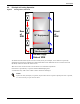
Description 3.2 Principle of Cooling Operation Figure 2 Cooling airflow, side view Fan Bank Rear of XDK 19" Equipment Front of XDK Air / Water Heat Exchanger Cold Water Supply Side of XDK Air that has been heated by the servers to 95°F (35°C), for example, is circulated to a specially designed air/water heat exchanger by high-performance fans. The heated air is cooled to 68-77°F (20-25°C) and fed to the front of the server. The server fans can draw in the air and feed it over internal components.
Description Table 2 Technical data Housing material Operating Temperature range Abs. atmospheric humidity Temperature difference across server Aluminium sheet, sheet steel, galvanized and coated 50°F to 95°F (10°C to 35°C) 8g / kg maximum approx. 15K Noise level 55 dB(A) sound pressure at a distance of 3 ft.
Description 3.3 Control The server cabinet temperature is controlled by the fan control board A temperature sensor continuously measures the temperature of the server cabinet (server feed air). The air circulation flow rate is controlled by the fan speed according to the current thermal load. At temperatures lower than 70°F (21°C) fans rotate at 75% of maximum speed. Between 68°F and 73°F (20 and 23°C), speed increases proportionally to the temperature up to 96% of maximum speed.
Description 3.4.1 Function Front and rear door are kept closed with two electromagnets. The door will be pushed open smoothly by a gas pressure spring if power to the electromagnets fails. If the doors are opened, the thermal load can escape into the room, preventing the servers from overheating. The inflow of air with water droplets can also be prevented (Door opening due to humidity alarm). When the rear door is opened, the fans shut down automatically.
Description 3.4.3 Manual Closing 1. Press LED switch for electromagnet activation 2. The LED lights up 3. Push door evenly shut. Both magnetic locks must latch. 3.4.4 Manual Opening 1. Press LED switch - green LED doesn’t light 2.
Equipment Inspection, Handling And Storage 4.0 EQUIPMENT INSPECTION, HANDLING AND STORAGE Upon arrival of the unit, and before unpacking, verify that the labeled equipment matches the bill of lading. Inspect all items for damage, either visible or concealed. Damage should be immediately reported to the carrier and a damage claim filed with a copy sent to your local sales representative. 4.1 Packaging Material All material used to package this unit is recyclable.
Equipment Inspection, Handling And Storage 4.3 Storage • If the XDK’s packaging has been removed, cover it with tarpaulins to protect against particulates, such as sand and dust, and from moisture. • Keep storage temperature between -22°F and 104°F (-30°C and +40°C). • The heat exchanger must be completely drained to prevent the risk of freezing damage. • When stored for more than 12 months, turn fans by hand to check the fan bearings prior to installation. 4.
Installation and Commissioning 5.0 INSTALLATION AND COMMISSIONING 5.1 Preparation for Installation ! ! CAUTION Risk of improper installation. Can cause equipment damage. Before installing the unit, a number of points must be checked for safety and to ensure the correct function of the server cabinet. Take care when performing these checks to ensure that the unit functions correctly. CAUTION Risk of improper installation. Can cause equipment damage. The XDK must be installed on a level surface.
Installation and Commissioning 5.3 Water Connection The heat exchanger can be pulled out for servicing Water pipes should be connected so that the heat exchanger can be pulled out when the connection is undone. If the heat exchanger is connected to the water circuit using threaded fittings, the pipe fitting must be supported on tightening. Before commissioning the server cabinet, the pipe connections should be checked for leaks according to local codes. 5.3.
Installation and Commissioning Figure 8 Heat exchanger 27-3/8" (695mm) 33-7/16" (850mm) Space for Cabling 9-7/8" (150mm) 2" (50mm) Top View Figure 9 2" (50mm) Heat exchanger connection Water return Water supply Liebert recommends insulating the cold water pipes with waterproof insulation to prevent condensation and losses.
Installation and Commissioning Figure 10 Bottom plate with cutouts Sealed Cable Cutout Rear Network Cable Entry Cutout for Water Pipes Condensed Water Cutouts Front Cable and pipe openings must be sealed air-tight on completion of work. 5.4 Condensed Water Connection If the XDK is operated below dew point, condensed water may occur. As standard there is a water connection, 5/8" diameter, in the condensed water tray for drainage.
Installation and Commissioning The condensate drain is not pressurized; a condensate pump can be used. 5.5 Electrical Connection The wiring diagram is enclosed in the unit. ! WARNING Risk of electric shock. Can cause injury or death. Disconnect all local and remote electric power supplies before working within. Prior to beginning installation, shut down the server cabinet, disconnect it and secure it against unauthorized startup.
Servicing and Maintenance 6.0 SERVICING AND MAINTENANCE ! WARNING ! WARNING ! CAUTION Risk of high speed rotating fan blades. Can cause serious injury. Disconnect all local and remote electric powers supplies and assure that fan blades have stopped rotating before working within the unit. Risk of electric shock. Can cause injury or death. Disconnect all local and remote electric power supplies before working within the unit. Risk of explosive discharge of water under pressure.
Servicing and Maintenance Reinstall the fan by reversing the steps to remove the fan. 1. Tighten the fan fastening bolts. 2. Connect the power supply cable to the fan. ! WARNING Risk of electric shock. Can cause injury or death. Reconnect the earth ground cable to the sheet metal panel to prevent a potentially hazardous open circuit in case of loose or disconnected electrical wiring or a fan motor short circuit. 3. Switch on the circuit breaker. 4. Dispose of the old fans correctly. 6.
Servicing and Maintenance 6.3 Replacing the Heat Exchanger Figure 12 Heat exchanger replacement Step 1: Lift the air duct off the flange to remove it. Step 4: Remove screws Step 5: Pull out the heat exchanger Step 3: Remove condensate connection Reinstall the heat exchanger by reversing the reverse order of removal.
Dismantling and Disposal 7.0 DISMANTLING AND DISPOSAL The XDK may be dismantled by qualified personnel only. ! WARNING Risk of electric shock. Can cause injury or death. Disconnect all local and remote electric power supplies before working within the unit. Disconnect the unit from the external water circuit by closing the shutoff valves and drain the unit’s water circuit. Transport the unit as described in 4.
Water Purity Requirements 8.0 WATER PURITY REQUIREMENTS To ensure the maximum service life of the air/water heat exchangers, water must comply with the VGB water regulations (VGB-R 455 P). The water used must be soft enough to prevent deposits, but it must not be so soft that heat exchanger corrosion occurs. The following table contains the most important impurities and methods for removing them.
Water Purity Requirements 8.1 Unit Installation Checklist ___ 1. Check unit for damage on delivery ___ 2. Check for level floor ___ 3. Check maximum floor load ___ 4. XDK feet adjusted, if applicable ___ 5. XDK is level ___ 6. No remains of packaging in the XDK ___ 7. All installation tools removed ___ 8. Cable entries into the unit correct and air-tight ___ 9. Cable connections checked ___ 10. Cold water connection does not leak ___ 11. Pressure test performed ___ 12. Water circuit bled ___ 13.
Water Purity Requirements 8.
Water Purity Requirements Configuration Table 8 Type of cabinet XDK 17kW Cabinet Number Serial Number Date Shipped Fan Type Table 9 Control of status General Condition Load Carrying Capacity Checked Yes No Level Alignment Checked Yes No Transportation Damages of Cabinet Yes No Damages on Heat Exchanger/Connections Yes No Front Door Closing Easily Yes No Yes No Yes No Yes No Yes No Comments Comments: Rear Door Closing Easily Comments: Cable Entries Closed Comments Condensate
Water Purity Requirements Table 10 Cold water facility on site Cold Water XDK Connected To Water Temperature Water Pressure Water Differential Pressure Table 11 Feed Feed °C/°F Return PSI (Pa) Return PSI (Pa) Pa Electrical data / documents Wiring Scheme Attached Yes No Cable Connections Checked: Yes No Electrical Acceptance Certificate by Approved Staff Yes No Function of All Fans (Air Blowing Direction) Yes No Fans Shut Down When Rear Door is Opened Yes No Yes No Yes No Com
Water Purity Requirements Table 12 Function check (continued) Malfunction Indicator Function Yes No Yes No Comments Condensate Occurrence at Heat Exchanger Comments Pressure Test Water Circuit Yes Water Flow Rate Adjusted Yes Flow Rate (Possible Only Externally) GPM Water Feed °F (°C) Water Return °F (°C) No Air Temperature in the Cabinet At The Heat Exchanger Inlet °F (°C) Air Temperature in the Cabinet At the Heat Exchanger Outlet °F (°C) Commissioning performed by day to day oper
Water Purity Requirements 26
Ensuring The High Availability 0f Mission-Critical Data And Applications. Emerson Network Power, the global leader in enabling business-critical continuity, ensures network resiliency and adaptability through a family of technologies—including Liebert power and cooling technologies—that protect and support business-critical systems. Liebert solutions employ an adaptive architecture that responds to changes in criticality, density and capacity.