
Installation Guide


q
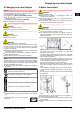
The
installation area of your appliance must demonstrate,
per 8 gof refrigerant R 600a, a volume of 1 m
3
according to
the EN 378 standard. If the installation area is too small, an
inflammable gas-air mixture may arise as a result of a
leakage in the refrigeration circuit. Information as to the
refrigerant amount can be found in the type plate on the
inside of the appliance.
q
If the appliance is installed in a very damp environment,
condensed water may form on the outside of the appliance.
Always make sure that there is good ventilation - both at air
inlet and outlet - at the site of installation.
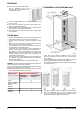
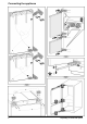
If the transport lock is inserted on the door:
u
Pull off red transport lock.
If the transport lock is screwed onto the door:
u
Unscrew
red transport lock.
Close the freed retaining hole
with plugs (60).
After installation:
u
Remove
protective films, adhesive tapes and transport lock
parts etc.
Note
u
Clean the appliance (see Operating Instructions,
Chapter "Cleaning the appliance").
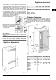
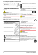
4 Appliance dimensions
Fig. 1
A
(mm)
B
(mm)
C
(mm)
D
(mm)
E
(mm)
ICP 29.. 559 544 1572 549 15
ICBP 32.. 559 544 1770 549 15
ICU 33.., ICUN 33..,
ICP 33.., ICNP 33..,
ICN 33.., SICN 33..,
ICBN 33.., SICBN 33..
559 544 1770 695 15
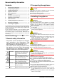
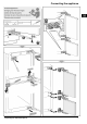
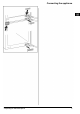
5 Recess dimensions
The
appliance is built-in and therefore completely enclosed by
a kitchen unit. The kitchen unit concerned must be built exactly
to the prescribed dimensions and allow for sufficient ventila-
tion, both at air inlet and outlet, to ensure proper appliance
operation.
Fig. 2
M
1
) : For N3366 only (see 9)
F
(mm)
G
(mm)
H
(mm)
J
(mm)
K
(mm)
L
(mm)
ICP 29.. 1574
—
1590
560
—
570
min.
560
min.
500
min.
40
max.
19
ICU 33..,
ICUN 33..,
ICP 33..,
ICNP 33..,
ICN 33..,
SICN 33..,
ICBP 32..,
ICBN 33..,
SICBN 33..
1772
—
1788
560
—
570
min.
560
min.
500
min.
40
max.
19
Appliance dimensions
* Depending on model and options 3