
Installation Guide


u
In the case of Side-by-Side installa-
tion, two appliances next to one
another, build the appliances into
separate kitchen units.
u
Check the wall thickness of the adjoining cabinets: it must
be min. 16 mm.
u
Only install the appliance in robust, stable kitchen units.
Secure the units against tipping.
u
Align the kitchen unit using a spirit level and marking square
and if necessary compensate with shims.
u
Ensure that the floor and walls of the unit are at right angles
to one another.
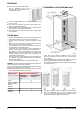
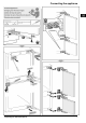
6 Unit door
-
Two doors are required for this kitchen unit: the upper for the
refrigerator and the lower for the freezer compartment.
-
The doors must be minimum 16 mm and maximum 19 mm
thick.
-
When both doors are closed, the gap between the upper
and lower door must be at least 3 mm high.
-
The gap between unit doors must be at the same level as
the gap between the appliance doors.
-
There must be a gap of minimum 3 mm in height between
the door and the unit door located above it (if one exists).
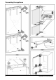
-
The width of the unit doors depends on the style of the
kitchen and on the gap size between the door panels of the
cabinet. Generally, there should remain a vertical gap of
3 mm between the unit doors.
-
The top edges of the upper and lower doors should be on a
level with the doors of the adjoining cabinet (or cabinets), if
there are other cabinets.
-
The unit doors must be planar and mounted stress-free.
NOTICE
Risk of damage from over-heavy unit door!
If the unit door is too heavy, damage to the hinges and resulting
impairment of function cannot be excluded.
u
Before mounting the unit door, make sure that the door does
not exceed the approved unit door weight.
Appliance type Maximum unit door weight (kg)
Refrigerator
compartment
door
Freezer compart-
ment door
ICP 29.. 13 12
ICU 33.., ICUN 33..,
ICP 33.., ICN 33..,
SICN 33..,
ICNP 33..
14 12
ICBP 32.. 19 12
ICBN 33..,
SICBN 33..
20 12
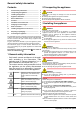
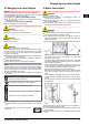
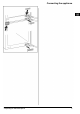
7 Ventilation of the kitchen unit
Fig. 3
-
There must be an effective ventilation shaft of at least
200 cm
2
per appliance at the air inlet
Fig. 3 (A)
and outlet
Fig. 3 (B)
vent.
-
The principle applies that the larger the ventilation shaft, the
more energy-saving the operation of the appliance.
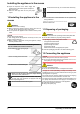
-
The depth of the ventilation shaft at the back of the cabinet
must be min. 40 mm.
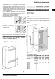
Fig. 4
-
The upper ventilation shaft can either be positioned directly
above the appliance with an optional ventilation grille
Fig. 4 (C)
, close to the ceiling above the unit
Fig. 4 (D)
or as
an air outlet opening in a false ceiling
Fig. 4 (E)
.
Unit door
4 * Depending on model and options