
Exercise Bike User Manual
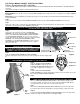

Life Fitness Models 9500HR / 9100 Exercise Bikes
Fitness Entertainment Kit Installation
(for use with Broadcast Vision Fitness Cinema and Fitness Cinema 900 and Cardio Theater Wireless and LCS Wireless
systems)
Tools Required: Phillips Screwdriver, Small Adjustable Wrench
Step 1
Model 9500HR: Remove the two screws securing the NECK SHROUD and carefully remove the user right half of the NECK SHROUD
ASSEMBLY.
Model 9100: Release the COLLAR by carefully depressing the user left and right sides inward until the COLLAR TABS disengage
from the SHROUDS.
Step 2
Remove the screw securing the SEAT SHROUD ASSEMBLY and remove the SEAT SHROUD ASSEMBLY from the frame.
Step 3
Remove the eight screws securing the user right SHROUD. Rotate the user right crank arm to the 12:00 position, cover the crank arm
with a cloth, and carefully remove the SHROUD from the frame.
NOTE: BE CAREFUL NOT TO DAMAGE THE SHROUD WHEN MANEUVERING IT
AROUND THE PEDAL AND CRANK SHAFT.
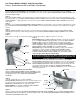
Step 4
Remove the nuts and washers from the ALTERNATOR
TERMINALS “B” and “E”. Place the red wire RING TERMINAL
(large) of the FITNESS ENTERTAINMENT CABLE ASSEMBLY
over ALTERNATOR TERMINAL “B” and secure the connector
with the appropriate nut and washer. Place the orange wire RING
TERMINAL of the FITNESS ENTERTAINMENT CABLE
ASSEMBLY over ALTERNATOR TERMINAL “E” and secure the
RING TERMINAL with the remaining nut and washer. Tighten
nuts to 25 - 30 in. lbs.
NOTE: DO NOT REMOVE THE EXISTING RING TERMINALS
FROM THE ALTERNATOR STUDS.
NOTE: TO AVOID POTENTIAL DAMAGE, BE SURE THE RING
TERMINALS OF THE FITNESS ENTERTAINMENT CABLE
ASSEMBLY FACE THE CENTER OF THE ALTERNATOR.
Step 5
Route the FITNESS ENTERTAINMENT CABLE ASSEMBLY
along the existing wire cluster and secure it near the existing wire tie with a supplied wire
tie.
NOTE: BE SURE TO LEAVE ADEQUATE STRAIN RELIEF OF THE FITNESS
ENTERTAINMENT CABLE ASSEMBLY AT THE ALTERNATOR.
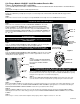
Step 6
Route the FITNESS ENTERTAINMENT
CABLE ASSEMBLY along the top of the
ALTERNATOR MOUNTING BRACKET and
secure with a supplied wire tie. (Figure 1)
Step 7
Feed the FITNESS ENTERTAINMENT
CABLE ASSEMBLY beneath the angled frame member and out the bottom front of the
bike behind the FRONT SHROUD BRACKET.
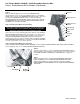
Step 8
NOTE: WITH A SUPPLIED ALCOHOL WIPE, CLEAN THE SHROUD AT EACH
CABLE CLAMP LOCATION BEFORE MOUNTING THE CABLE CLAMPS.
Place one ADHESIVE BACKED CABLE CLAMP 1” down from the top ridge of the
user left shroud and 1/2” from the inner edge. Position the CABLE CLAMP with the
opening facing the inner edge of the user left shroud. (Figure 2)
Step 9
Place another ADHESIVE BACKED CABLE CLAMP at the bottom front edge of the
user left shroud. Position the clamp with the opening facing the outside of the bike.
Step 10
Insert the FITNESS ENTERTAINMENT CABLE ASSEMBLY into the top cable clamp
leaving a 20” length extending from the top CABLE CLAMP.
Terminal “B”
Terminal “E”
1“
Cable
Clamp
User
Left
Shrou
d
Cable Tie
Terminal “E”
Terminal “B”
Alternator
Mounting Bracket
Cable Assembly
(Bundle Excess)
Front Shroud
Bracket
Front Shroud
Opening
Fi
g
ure 1
Fi
g
ure 2