
Exercise Bike User Manual

Life Fitness Models 9500HR / 9100 Exercise Bikes
Fitness Entertainment Kit Installation (Continued)
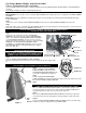
Step 11
Run the FITNESS ENTERTAINMENT CABLE ASSEMBLY down the front of the user left shroud making certain the FITNESS
ENTERTAINMENT CABLE ASSEMBLY lays flat against the shroud. Insert the FITNESS ENTERTAINMENT CABLE ASSEMBLY into
the bottom CABLE CLAMP.
Step 12
Place a third CABLE CLAMP on the underside of the user left shroud front as close to the frame as possible (approximately 1” from
the frame). Pull the excess FITNESS ENTERTAINMENT CABLE ASSEMBLY back into the bike until the FITNESS ENTERTAINMENT
CABLE ASSEMBLY is tight against the user left shroud. Insert the FITNESS ENTERTAINMENT CABLE ASSEMBLY into the third
cable clamp.
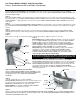
Step 13
Bundle the excess FITNESS ENTERTAINMENT CABLE ASSEMBLY as shown in Figure 1 and secure with a supplied wire tie. Secure
the bundled FITNESS ENTERTAINMENT CABLE ASSEMBLY to the frame away from moving parts as shown with another supplied
cable tie.
Step 14
Apply two CABLE CLAMPS to the front of the user left shroud in-line and between the two previously installed CABLE CLAMPS
alternating the direction of the cable clamp openings. Insert the FITNESS ENTERTAINMENT CABLE ASSEMBLY into the CABLE
CLAMPS.
Step 15
Reverse steps 1 through 3 to return all shroud parts to their proper positions. Tighten screws to 12 - 15 in. lbs.
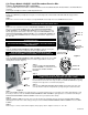
Step 16
Model 9500HR: Apply a CABLE CLAMP approximately 3” down from the bend in
the user left NECK SHROUD and approximately 1/4” from the NECK SHROUD
OVERLAP JOINT. Position the CLAMP with the opening facing the NECK
SHROUD OVERLAP JOINT. Continue routing the FITNESS ENTERTAINMENT
CABLE ASSEMBLY upwards flat against the shroud and insert the FITNESS
ENTERTAINMENT CABLE ASSEMBLY into the CABLE CLAMP.
Model 9100: Apply a CABLE CLAMP approximately 1/2 way up the handlebar
vertical tube. Continue routing the FITNESS ENTERTAINMENT CABLE
ASSEMBLY upwards flat against the handlebar vertical tube and insert the
FITNESS ENTERTAINMENT CABLE ASSEMBLY into the CABLE CLAMP.
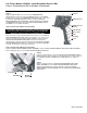
Step 17 (Cardio Theater Wireless System Only)
NOTE: WITH A SUPPLIED ALCOHOL WIPE, CLEAN THE SHROUD AT EACH
HOOK AND LOOP FASTENING STRIP LOCATION BEFORE MOUNTING THE
HOOK AND LOOP FASTENING STRIPS.
Remove the four screws and mounting block from the back of the FITNESS
ENTERTAINMENT RECEIVER. Remove the backing on one side of the hook and
loop fastening strips provided and apply lengthwise to the back of the FITNESS
ENTERTAINMENT RECEIVER. Remove the backing of the remaining side of the
hook and loop fastening strips and apply the FITNESS ENTERTAINMENT
RECEIVER to the underside of the DISPLAY CONSOLE as shown. Press firmly to
ensure proper adhesion.
Step 18 (Cardio Theater Wireless System Only)
Plug the FITNESS ENTERTAINMENT CABLE ASSEMBLY and the
FITNESS ENTERTAINMENT TOUCHPAD CABLE ASSEMBLY into
the appropriate jacks on the FITNESS ENTERTAINMENT
RECEIVER.
Step 19
Using two supplied wire ties, mount the FITNESS
ENTERTAINMENT TOUCH PAD to the bike. Controller location is at
the discretion of the customer. Refer to the CARDIO THEATER or
BROADCAST VISION MANUAL for suggested locations.
Model 9500HR: Do not install the FITNESS ENTERTAINMENT
TOUCH PAD over the Lifepulse
®
electrodes.
Step 20
Plug the remaining end of the FITNESS ENTERTAINMENT TOUCHPAD CABLE ASSEMBLY into the FITNESS ENTERTAINMENT
TOUCHPAD (
Cardio Theater Wireless System). Plug the end of the FITNESS ENTERTAINMENT CABLE ASSEMBLY into the
FITNESS ENTERTAINMENT TOUCHPAD.
Receiver
Cable Assembly
Display
Console
User Left
Neck Shroud
Cable
Clamp
Display
Console
Receiver
Touch Pad
Touch Pad Cable
Handlebar