
Installation Guide
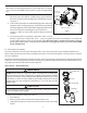

f. Hold the impeller securely in place and remove the impeller lock screw by using a #2 Phillips screwdriver.
The screw is a left-handed thread and loosens in a clockwise direction.
g. Remove the shaft cap located at the back of the motor and hold the shaft secure with a ½ inch open-end
wrench.
h. To unscrew the impeller from the shaft, twist the impeller counter-clockwise.
i. Remove the four bolts from the seal plate to the motor, using a 9/16 inch wrench.
j. If replacing the mechanical seal set, see Section B. Pump Reassembly/Seal Replacement on below.
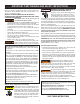
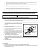
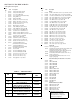
B. Pump Reassembly/Seal Replacement; see Figure 4.
NOTE
It is important that the O-rings be kept clean and well lubricated. We recommend a silicone base lubricant for best results.
CAUTION
Be sure not to scratch or mar the polished shaft seal faces; the seal will leak if faces are damaged.
1. When installing the replacement shaft seal, use silicone sealant on the metal portion before pressing into the seal plate,
being careful to keep off of the seal face. Ensure the seal is fully seated and allow 24 hours for sealant to cure. (Complete
seal plate w/seal replacement kit available, P/N 350201/350101.)
2. Before installing the ceramic section of the seal into the impeller, be sure the impeller is clean. Use a light density soap
and water to seal the seal. Press the seal into the impeller with
your thumbs and wipe off the ceramic and carbon faces with a
clean cloth.
3. Remount the seal plate to the motor by installing bolts in an X
pattern and tightening to 70 in-lbs.
4. Clean the motor shaft thread and the impeller insert, then screw
the impeller onto the motor shaft.
5. Screw in the impeller lock screw (counter-clockwise and
tighten to 25 in-lbs. while holding the motor shaft with wrench).
6. Remount the diffuser onto the seal plate. Make sure the plastic
pins and holding screw inserts are aligned.
7. Grease the diffuser O-ring and seal plate gasket.
8. Grease the bolt threads, assemble the motor sub-assembly to the
strainer pot-pump body by using the two through bolts for proper
alignment. Do not tighten the through bolts until all 6 bolts are in place and finger tightened. Torque in a cross pattern
to 110 in-lbs.
9. Fill the pump with water.
10. Reinstall the pump lid and plastic clamp; see SECTION IV. RESTART INSTRUCTIONS.
11. Reprime the system.
C. The Shaft Seal.
1. The Shaft Seal consists primarily of two parts, a rotating member and a ceramic seal.
2. The pump requires little or no service other than reasonable care, however, a Shaft Seal may occasionally become
damaged and must be replaced.
Lockscrew
Lockscrew Seal
Gasket
Seal Plate
Bolt
Water Slinger
Motor Shaft
Impeller
Figure 4.
5