
Datasheet

5
LT1360
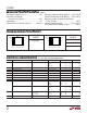
Note 1: Absolute Maximum Ratings are those values beyond which the life
of a device may be impaired.
Note 2: Differential inputs of ±10V are appropriate for transient operation
only, such as during slewing. Large, sustained differential inputs will cause
excessive power dissipation and may damage the part. See Input
Considerations in the Applications Information section of this data sheet
for more details.
Note 3: A heat sink may be required to keep the junction temperature
below absolute maximum when the output is shorted indefinitely.
Note 4: Input offset voltage is pulse tested and is exclusive of warm-up drift.
Note 5: Slew rate is measured between ±10V on the output with ±6V input
for ±15V supplies and ±2V on the output with ±1.75V input for ±5V supplies.
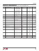
SYMBOL PARAMETER CONDITIONS V
SUPPLY
MIN TYP MAX UNITS
V
OS
Input Offset Voltage (Note 4) ±15V ● 2.0 mV
±5V
● 2.0 mV
±2.5V
● 2.2 mV
Input V
OS
Drift (Note 7) ±2.5V to ±15V ● 912 µV/°C
I
OS
Input Offset Current ±2.5V to ±15V ● 400 nA
I
B
Input Bias Current ±2.5V to ±15V ● 1.8 µA
CMRR Common Mode Rejection Ratio V
CM
= ±12V ±15V ● 84 dB
V
CM
= ±2.5V ±5V ● 77 dB
V
CM
= ±0.5V ±2.5V ● 66 dB
PSRR Power Supply Rejection Ratio V
S
= ±2.5V to ±15V ● 90 dB
A
VOL
Large-Signal Voltage Gain V
OUT
= ±12V, R
L
= 1k ±15V ● 2.5 V/mV
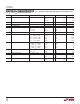
V
OUT
= ±10V, R
L
= 500Ω±15V ● 1.5 V/mV
V
OUT
= ±2.5V, R
L
= 500Ω±5V ● 1.5 V/mV
V
OUT
= ±2.5V, R
L
= 150Ω±5V ● 0.6 V/mV
V
OUT
= ±1V, R
L
= 500Ω±2.5V ● 1.3 V/mV
V
OUT
Output Swing R
L
= 1kΩ, V
IN
= ±40mV ±15V ● 13.4 ±V
R
L
= 500Ω, V
IN
= ±40mV ±15V ● 12.0 ±V
R
L
= 500Ω, V
IN
= ±40mV ±5V ● 3.4 ±V
R
L
= 150Ω, V
IN
= ±40mV ±5V ● 3.0 ±V
R
L
= 500Ω, V
IN
= ±40mV ±2.5V ● 1.2 ±V
I
OUT
Output Current V
OUT
= ±12.0V ±15V ● 24 mA
V
OUT
= ±3.0V ±5V ● 20 mA
I
SC
Short-Circuit Current V
OUT
= 0V, V
IN
= ±3V ±15V ● 30 mA
SR Slew Rate A
V
= –2, (Note 5) ±15V ● 450 V/µs
±5V
● 175 V/µs
I
S
Supply Current ±15V ● 6.0 mA
±5V ● 5.8 mA
Note 6: Full power bandwidth is calculated from the slew rate
measurement: FPBW = SR/2πV
P
.
Note 7: This parameter is not 100% tested.
Note 8: The LT1360C is guaranteed functional over the operating
temperature range of –40°C to 85°C.
Note 9: The LT1360C is guaranteed to meet specified performance from
0°C to 70°C. The LT1360C is designed, characterized and expected to
meet specified performance from –40°C to 85°C, but is not tested or QA
sampled at these temperatures. For guaranteed I-grade parts, consult the
factory.
ELECTRICAL CHARACTERISTICS
The ● denotes the specifications which apply over the temperature range
–40°C ≤ T
A
≤ 85°C, V
CM
= 0V unless otherwise noted. (Note 9)