USER GUIDE BUSINESS SERIES 8-Port 10/100/1000 Managed Gigabit Switch Model: SRW2008/SRW2008P/SRW2008MP
About This Guide About This Guide Icon Descriptions While reading through the User Guide you may see various icons that call attention to specific items. Below is a description of these icons: NOTE: This check mark indicates that there is a note of interest and is something that you should pay special attention to while using the product. WARNING: This exclamation point indicates that there is a caution or warning and it is something that could damage your property or product.
Table of Contents Chapter 1: Introduction 1 Welcome . . . . . . . . . . . . . . . . . . . . . . . . . . . . . . . . . . . . . . . . . . . . . . . . . . . . 1 Chapter 2: Product Overview 2 SRW2008 - Front Panel . . . . . . . . . . . . . . . . . . . . . . . . . . . . . . . . . . . . . . . . . . . 2 LEDs . . . . . . . . . . . . . . . . . . . . . . . . . . . . . . . . . . . . .
Table of Contents SNTP Servers . . . . . . . . . . . . . . . . . . . . . . . . . . . . . . . . . . . . . . . . . . . . . 19 Port Management > Port Settings . . . . . . . . . . . . . . . . . . . . . . . . . . . . . . . . . . . 19 Port Configuration Detail . . . . . . . . . . . . . . . . . . . . . . . . . . . . . . . . . . . . . 20 Port Management > Link Aggregation . . . . . . . . . .
Table of Contents QoS > Advanced Mode . . . . . . . . . . . . . . . . . . . . . . . . . . . . . . . . . . . . . . . . . 38 Out of Profile DSCP . . . . . . . . . . . . . . . . . . . . . . . . . . . . . . . . . . . . . . . . . 39 Policy Name . . . . . . . . . . . . . . . . . . . . . . . . . . . . . . . . . . . . . . . . . . . . . . 39 New Class Map . . . . . . . . . . . .
Table of Contents Admin > Memory Logs . . . . . . . . . . . . . . . . . . . . . . . . . . . . . . . . . . . . . . . . . . 56 Admin > Flash Logs . . . . . . . . . . . . . . . . . . . . . . . . . . . . . . . . . . . . . . . . . . . . 56 Appendix A: About Gigabit Ethernet and Fiber Optic Cabling 57 Gigabit Ethernet . . . . . . . . . . . . . . . . . . . . . . . . . . . . . . . . . . . . .
Chapter 1 Chapter 1: Introduction Welcome This guide covers three product models. •• SRW2008 8-port 10/100/1000 Ethernet Switch with WebView. Includes 8 10/100/1000 RJ-45 ports and 2 shared MiniGBIC slots. •• SRW2008MP 8-port 10/100/1000 Ethernet Switch with WebView and Maximum POE (Power over Ethernet) Includes 8 10/100/1000 RJ-45 ports and 2 shared MiniGBIC slots.
Product Overview Chapter 2 Chapter 2: Product Overview miniGBIC1/2 The mini-GBIC (gigabit interface converter) port is a connection point for a mini-GBIC expansion module, so the Switch can be uplinked via fiber to another switch. Each MiniGBIC port provides a link to a high-speed network segment or individual workstation at speeds of up to 1000Mbps. SRW2008 - Front Panel The LEDs and ports are located on the front panel of the Switch.
Chapter 2 Product Overview miniGBIC1/2 The mini-GBIC (gigabit interface converter) port is a connection point for a mini-GBIC expansion module, so the Switch can be uplinked via fiber to another switch. Each MiniGBIC port provides a link to a high-speed network segment or individual workstation at speeds of up to 1000Mbps. Use the Linksys MGBT1, MGBSX1, or MGBLH1 mini-GBIC modules with the Switch.
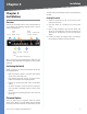
Installation Chapter 3 Chapter 3: Installation 1U high rack for rack-mount placement, or horizontally on the wall. Overview 1. Attach the rubber feet to the recessed areas on the bottom of the Switch. This chapter will explain how to connect network devices to the Switch. The following diagram shows a typical network configuration. 2. Place the Switch on a desktop near an AC power source. Internet Cable/ DSL Modem Router Desktop Placement Uplink via Fiber to Switch Administrator’s Notebook 3.
Installation Chapter 3 Rack-Mount Placement When rack-mounting the Switch, please observe the following guidelines: •• Elevated Operating Ambient If installed in a closed 3. Make sure the brackets are properly attached to the Switch. 4. Use the appropriate screws (not included) to securely attach the brackets to your rack. or multi-unit rack assembly, the operating ambient temperature of the rack environment may be greater than room ambient.
Installation Chapter 3 Print this page at 100% size, cut along the dotted line and place on the wall to drill precise spacing. Wall-Mount Placement When mounting the Switch on the wall, the Switch should be mounted horizontally. The front panel should face either up or down. The unit should not be positioned vertically when mounted. You will need two suitable screws to mount the Switch. Use the template above to plan your installation.
Chapter 3 Installation Hardware Installation To connect network devices to the Switch, follow these instructions: 1. Make sure all the devices you will connect to the Switch are powered off. 2. For 10/100Mbps devices, connect a Category 5 Ethernet network cable to one of the numbered ports on the Switch. For a 1000Mbps device, connect a Category 5e Ethernet network cable to one of the numbered ports on the Switch. 3. Connect the other end to a PC or other network device. 4.
Chapter 4 Chapter 4: Configuration Using the Console Interface Configuration Using the Console Interface 4. Select a port to communicate with the switch. Select COM1, COM2, or TCP/IP. Overview The Switch features a menu-driven console interface for basic configuration of the Switch and management of your network. The Switch can be configured using CLI through the console interface or through a telnet connection. This chapter describes console interface configuration.
Chapter 4 Configuration Using the Console Interface System Configuration Menu Press the Esc button and you will return to the login screen. Use the right arrow button to navigate to Execute and press the Enter button to enter the CLI interface. Configuring the Switch through the Console Interface The console screens consist of a series of menus. Each menu has several options, which are listed vertically.
Configuration Using the Console Interface Chapter 4 Versions Management Settings The Versions screen displays the Boot Version, Software Version, Loader Version and the Hardware Version. From the Management Settings screen, you can set Serial Port Session Configuration, Telnet Session Configuration, or Secure Telnet (SSH) Configuration. Versions Boot Version This file runs when the Switch is turned on. It performs power-on diagnostics and loads the operating system for the Switch.
Chapter 4 Configuration Using the Console Interface Telnet Configuration SSH Server Configuration SSH Configuration SSH Status On the SSH Configuration screen, you can select SSH Server Configuration, SSH Server Status, SSH Crypto Key Generation, and SSH Keys Fingerprints. The SSH Status screen displays whether the SSH Server is enabled, the RSA and DSA key status, and any open SSH sessions. Select Refresh to update the screen if necessary. To exit, select Quit and press the Enter key.
Chapter 4 Configuration Using the Console Interface NOTE: The Username & Password Settings screen can also be used to set passwords for other users. Security Settings The Security Settings screen enables you to configure security settings on the Switch, as well as generate and display the certificate. SSH Crypto Key Generation SSH Keys Fingerprints On the SSH Keys Fingerprints screen, the RSA and DSA keys will be displayed if they have been generated. Select Refresh to update the screen if necessary.
Chapter 4 SSL Certificate Generation Show Certificate Use the Show Certificate screen to display the internal certificate. Configuration Using the Console Interface IP Address Configuration The IP Address Settings screen allows you to set the IP information for the Switch. IP Address Configuration SSL Certificate Disable Active Management Profile Selecting this option will prompt you to confirm that you want to disable the Active Management Profile.
Configuration Using the Console Interface Chapter 4 Ping The Ping screen displays the IP address of the location you want to contact. HTTP HTTPS Configuration Use the HTTPS Configuration screen to configure HTTPS settings. You can enable or disable the HTTPS server and configure the port on which the session is enabled. Select Edit and press the Enter key to make changes. When your changes are complete, press the Esc key to return to the Action menu.
Chapter 4 Configuration Using the Console Interface File Management Reboot System The File Management screen allows you to upload or download files, such as the startup configuration, boot, or image file, using a TFTP server. Select Reboot System and press the Enter key if you want to restart the Switch. You will be asked if you want to continue. Press the y key to reboot the Switch, or press the n key to cancel. After the Switch has rebooted, the Switch Main Menu screen will appear.
Chapter 4 Configuration Using the Console Interface The Port Configuration screen displays the port numbers, their status, auto-negotiation status, speed and duplex mode, and status of flow control, which is the flow of packet transmissions. Select Edit and press the Enter key to make changes. When your changes are complete, press the Esc key to return to the Action menu. Select Save and press the Enter key to save your changes. To exit, select Quit and press the Enter key.
Chapter 5 Chapter 5: Advanced Configuration Overview This chapter describes the features included in the Webbased Utility. All of the features shown in this chapter, unless specifically identified, are included in the all of Fast Ethernet switches. Additional features for specific switches are noted. Accessing the Web-based Utility NOTE: The web-based utility is optimized for viewing with a screen resolution of 1024 x 768. Internet Explorer version 5.5 or above is recommended.
Advanced Configuration Chapter 5 Address Mode Indicates whether the Switch is configured with a Static or Dynamic IP address (configurable from Setup - Network Settings tab). Setup > Network Settings Base MAC Address This is the MAC address of the Switch. System Information Serial Number The serial number of the Switch is displayed. Model Name The model name of the Switch is displayed. Hardware version The current hardware version is displayed. Boot Version The current boot version is displayed.
Advanced Configuration Chapter 5 DNS Server Enter the primary DNS Server information. Daylight Saving Click the Save Settings button to save your changes or click Cancel Changes to discard the information. Daylight Saving Select Daylight Saving to enable it on the Switch. If the Switch should use US daylight savings, then select USA. If the Switch should use EU daylight savings, then select European.
Chapter 5 Speed The connection speed of the port is displayed here. The speed can be configured only when auto-negotiation is disabled on that port. Port Management > Port Settings Duplex This is the port duplex mode, Full (transmission occurs in both directions simultaneously) or Half (transmission occurs in only one direction at a time). This mode can be configured only when auto-negotiation is disabled and port speed is set to 10Mbps or 100Mbps.
Advanced Configuration Chapter 5 •• Max Capability Indicates that the port speeds and duplex mode settings can be accepted. Port Management > Link Aggregation •• 10 Half Indicates that the port is advertising a 10Mbps half duplex mode setting. •• 10 Full Indicates that the port is advertising a 10Mbps full duplex mode setting. •• 100 Half Indicates that the port is advertising a 100Mbps half duplex mode setting. •• 100 Full Indicates that the port is advertising a 100Mbps full duplex mode setting.
Chapter 5 Advanced Configuration Current Status Indicates if the LAG is currently operating. Reactivate Suspended LAG Reactivates a LAG if the LAG has been disabled as a result of a port lock or ACL operation. Admin Auto Negotiation Enables or disables Auto Negotiation on the LAG. Auto-negotiation is a protocol between two link partners that enables a LAG to advertise its transmission rate, duplex mode and flow control (the flow control default is disabled) abilities to its partner.
Advanced Configuration Chapter 5 Admin Status Indicates whether PoE is enabled or disabled on the port. Priority Indicates the PoE priority setting of the port. The possible values are: Critical, High and Low. The default is Low. Power Allocation (milliwatts) Indicates the actual amount of power the device can supply. VLAN Table The VLAN Table displays a list of all configured VLANs. The VLAN ID, VLAN Name, and status of the VLAN are displayed here. To remove a VLAN, click the Remove button.
Chapter 5 PVID Assigns a VLAN ID to untagged packets. The possible values are 2 to 4094. VLAN 4095 is defined as per standard and industry practice as the discard VLAN. Packets classified to the Discard VLAN are dropped. Ingress Filtering Enables or disables Ingress filtering on the port. Ingress filtering discards packets which do not include an ingress port. LAG Indicates the LAG to which the VLAN is defined.
Advanced Configuration Chapter 5 LAG Indicates if the port is a member of a LAG. If it is a member of a LAG, it cannot be configured to a VLAN. The LAG to which it belongs can be configured to a VLAN. •• Port Indicates the port number on which GVRP is enabled. •• LAG Indicates the LAG number on which GVRP is enabled. Join VLAN Detail The Join VLAN Detail screen allows you to select the VLAN for the port selected and determine whether it is tagged or untagged.
Advanced Configuration Chapter 5 •• 30 Sec Indicates that the RMON statistics are refreshed every 30 seconds. •• 60 Sec Indicates that the RMON statistics are refreshed every 60 seconds. Drop Events Displays the number of dropped events that have occurred on the interface since the device was last refreshed. Refresh Now button Use this option to refresh the statistics. Statistics > RMON History The RMON History screen contains information about samples of data taken from ports.
Chapter 5 Current Number of Samples Displays the current number of samples taken. RMON History Advanced Configuration CRC Align Errors Displays the number of CRC and Align errors that have occurred on the interface since the device was last refreshed. Undersize Packets Displays the number of undersized packets (less than 64 octets) received on the interface since the device was last refreshed.
Advanced Configuration Chapter 5 •• Port Displays the RMON statistics for the selected port. •• LAG Displays the RMON statistics for the selected LAG. Counter Name Displays the selected MIB variable. Sample Type Defines the sampling method for the selected variable and comparing the value against the thresholds. The possible field values are: •• Absolute Compares the values directly with the thresholds at the end of the sampling interval.
Advanced Configuration Chapter 5 The Add to List button adds the configured RMON event to the Event Table at the bottom of the screen. •• 15 Sec Indicates that the statistics are refreshed every The Event Table area contains the following additional field: •• 30 Sec Indicates that the statistics are refreshed every 15 seconds. 30 seconds. •• 60 Sec Indicates that the statistics are refreshed every 60 seconds. Statistics > 802.1x Statistics The 802.
Advanced Configuration Chapter 5 Statistics > GVRP Statistics The GVRP Statistics screen contains device statistics for GVRP. Leave All Displays the device GVRP Leave all statistics. The GVRP Error Statistics Table contains the following fields: Invalid Protocol ID Displays the device GVRP Invalid Protocol ID statistics. Invalid Attribute Type Displays the device GVRP Invalid Attribute ID statistics. Invalid Attribute Value Displays the device GVRP Invalid Attribute Value statistics.
Chapter 5 •• Deny Drops packets which meet the ACL criteria. •• Shutdown Drops packet that meets the ACL criteria, and disables the port to which the packet was addressed. Ports are reactivated from the Port Management screen. Protocol Creates an ACE (Access Control Event) based on a specific protocol. Select from List Selects from a protocols list on which ACE can be based. The possible field values are: •• Any Matches the protocol to any protocol.
Chapter 5 The MAC Based ACL screen allows a MAC based ACL to be defined. ACEs can be added only if the ACL is not bound to an interface. Advanced Configuration Security > ACL Binding ACL Name Displays the user-defined MAC based ACLs. New ACL Name Specifies a new user-defined MAC based ACL name. Delete ACL Deletes the selected ACL. Action Indicates the ACL forwarding action. Possible field values are: •• Permit Forwards packets which meet the ACL criteria.
Chapter 5 Remote Authorization Dial-In User Service (RADIUS) servers provide additional security for networks. RADIUS servers provide a centralized authentication method for web access. Advanced Configuration protocol exchanges between the device and TACACS+ server. IP Address The Authentication Server IP address. Priority The server priority. The possible values are 065535, where 1 is the highest value. The RADIUS Server priority is used to configure the server query order.
Chapter 5 Security > 802.1x Settings Advanced Configuration Reauthentication Period Specifies the number of seconds in which the selected port is reauthenticated (Range: 300-4294967295). The field default is 3600 seconds. Quiet Period Specifies the number of seconds that the switch remains in the quiet state following a failed authentication exchange (Range: 0-65535).
Advanced Configuration Chapter 5 to that port (either it was learned on a different port, or it is unknown to the system), the protection mechanism is invoked, and can provide various options. Unauthorized packets arriving at a locked port are either: Trap Frequency The amount of time (in seconds) between traps. The default value is 10 seconds. •• Forwarded The Multiple Hosts screen allows network managers to configure advanced port-based authentication settings for specific ports and VLANs.
Advanced Configuration Chapter 5 Number of Violations Indicates the number of packets that arrived on the interface in single-host mode, from a host whose MAC address is not the supplicant MAC address. Security > Storm Control Port Displays the port number for which storm control is enabled.
Chapter 5 •• Basic Enables QoS on the interface. •• Advanced Enables Advanced mode QoS on the interface. Class of Service Specifies the CoS priority tag values, where zero is the lowest and 7 is the highest. Advanced Configuration % of WRR Bandwidth Displays the amount of bandwidth assigned to the queue. These values are fixed and are not user defined. QoS > DSCP Settings Queue Defines the traffic forwarding queue to which the CoS priority is mapped. Four traffic priority queues are supported.
Chapter 5 Modifying queue scheduling affects the queue settings globally. The Bandwidth screen is not used with the Service mode, as bandwidth settings are based on services. Queue shaping can be based per queue and/or per interface. Shaping is determined by the lower specified value. The queue shaping type is selected in the Bandwidth screen. Interface Indicates the interface for which the queue shaping information is displayed.
Advanced Configuration Chapter 5 Out of Profile DSCP New Class Map Advanced Mode > Out of Profile DSCP DSCP In Displays the DSCP In value. DSCP Out Displays the current DSCP out value. A new value can be selected from the pull-down menu. Advanced Mode > New Class Map Class Map Name Defines a new Class Map name The Policy Settings button opens the Policy Name screen. Preferred ACL Indicates if packets are first matched to an IP based ACL or a MAC based ACL.
Advanced Configuration Chapter 5 Aggregate Policer Settings The Aggregate Policer button opens the New Aggregate Policer screen. New Aggregate Policer •• Multiple STP Provides full connectivity for packets allocated to any VLAN. Multiple STP is based on the RSTP. In addition, Multiple STP transmits packets assigned to different VLANs through different MST regions. MST regions act as a single bridge.
Advanced Configuration Chapter 5 Root Forward delay (sec) Indicates the device forward delay time. The Forward Delay Time indicates the amount of time in seconds a bridge remains in a listening and learning state before forwarding packets. The default is 15 seconds. The range is 4 to 30 seconds. Topology Changes Counts Indicates the total amount of STP state changes that have occurred.
Advanced Configuration Chapter 5 Spanning Tree > STP Port Settings •• Forwarding Indicates that the port is in Forwarding mode. The port can forward traffic and learn new MAC addresses. Speed Indicates the speed at which the port is operating. Path Cost Indicates the port contribution to the root path cost. The path cost is adjusted to a higher or lower value, and is used to forward traffic when a path being rerouted. Default Path Cost When selected the default path cost is implemented.
Advanced Configuration Chapter 5 network topologies that allow a faster STP convergence without creating forwarding loops. Interface Displays the port or LAG on which Rapid STP is enabled. Role Indicates the port role assigned by the STP algorithm in order to provide to STP paths. The possible field values are: •• Root Provides the lowest cost path to forward packets to root switch. •• Designated Indicates that the port or LAG via which the designated switch is attached to the LAN.
Advanced Configuration Chapter 5 Spanning Tree > MSTP Instance Settings Spanning Tree > MSTP Interface Settings Spanning Tree > MSTP Instance Settings Spanning Tree > MSTP Interface Settings MSTP operation maps VLANs into STP instances. Packets assigned to various VLANs are transmitted along different paths within Multiple Spanning Trees Regions (MST Regions). Regions are one or more Multiple Spanning Tree bridges by which frames can be transmitted.
Advanced Configuration Chapter 5 •• Root Provides the lowest cost path to forward packets to root device. Multicast > IGMP Snooping •• Designated Indicates the port or LAG via which the designated device is attached to the LAN. •• Alternate Provides an alternate path to the root device from the root interface. •• Backup Provides a backup path to the designated port path toward the Spanning Tree leaves. Backup ports occur only when two ports are connected in a loop by a point-to-point link.
Advanced Configuration Chapter 5 Leave Timeout Indicates the amount of time the host waits, after requesting to leave the IGMP group and not receiving a Join message from another station, before timing out. If a Leave Timeout occurs, the switch notifies the Multicast device to stop sending traffic The Leave Timeout value is either user-defined, or an immediate leave value. The default timeout is 10 seconds.
Advanced Configuration Chapter 5 SNMP > Views SNMP > Global Parameters Local Engine ID Indicates the local device engine ID. The field value is a hexadecimal string. Each byte in hexadecimal character strings consists of two hexadecimal digits. Each byte can be separated by a period or a colon. The Engine ID must be defined before SNMPv3 is enabled. For standalone devices, select a default Engine ID that is comprised of Enterprise number and the default MAC address.
Advanced Configuration Chapter 5 SNMP > Group Profile •• Notify Sends traps for the assigned SNMP view. SNMP > Group Membership SNMP > Group Profile The Group Profile screen provides information for creating SNMP groups and assigning SNMP access control privileges to SNMP groups. Groups allow network managers to assign access rights to specific device features, or features aspects. Group Name Displays the user-defined group to which access control rules are applied.
Advanced Configuration Chapter 5 performed via HMAC-SHA-96 authentication. Password Define the local user password. Local user passwords can contain up to 159 characters. Authentication Key Defines the HMAC-MD5-96 or HMAC-SHA-96 authentication level. The authentication and privacy keys are entered to define the authentication key. If only authentication is required, 16 bytes are defined. If both privacy and authentication are required, 32 bytes are defined.
Advanced Configuration Chapter 5 Advanced Table Management Station Displays the management station IP address for which the basic SNMP community is defined. Community String Displays the password used to authenticate the management station to the device. Group Name Displays advanced SNMP communities group name. SNMP > Notification Filter The Add to List button adds the Notification Filter configuration to the Notification Filter Table at the bottom of the screen.
Chapter 5 UDP Port Displays the UDP port used to send notifications. The default is 162. Filter Name Indicates if the SNMP filter for which the SNMP Notification filter is defined. Timeout Indicates the amount of time (seconds) the device waits before resending informs. The default is 15 seconds. Retries Indicates the amount of times the device resends an inform request. The default is 3 seconds.
Advanced Configuration Chapter 5 •• Delete on Reset The MAC address is deleted when the device is reset. •• Delete on Timeout The MAC address is deleted when a timeout occurs. •• Secure The MAC Address is defined for locked ports. address is erased, and includes parameters for querying and viewing the Dynamic MAC Address table. The Dynamic MAC Address table contains address parameters by which packets are directly forwarded to the ports.
Advanced Configuration Chapter 5 all error reporting. For example, Syslog and local device reporting messages are assigned a severity code, and include a message mnemonic, which identifies the source application generating the message. It allows messages to be filtered based on their urgency or relevancy. Each message severity determines the set of event logging devices that are sent per each event logging. Logging Indicates if device global logs for Cache, File, and Server Logs are enabled.
Advanced Configuration Chapter 5 Cable Length This is the approximate length of the cable. The Cable Length test can be performed only when the port is up and operating at 1Gbps. Admin > Save Configuration Via HTTP This HTTP Firmware Upgrade screen is used for saving configuration information using your web browser. Upgrade Select this option to upgrade the switch from a file on the local hard drive. •• Source File Type in the name and path of the file or click Browse to locate the upgrade file.
Chapter 5 NOTE: When downloading a configuration file, make sure that it is a valid configuration file. If you have edited the file, ensure that only valid entries have been configured. Admin > Reboot Advanced Configuration NOTE: Restoring the factory defaults will erase all configuration settings that you have made. You can save a backup of your current configuration settings from the Admin > Save Configuration screen.
Chapter 5 Admin > Memory Logs The Memory Log screen contains all system logs in a chronological order that are saved in RAM (Cache). Advanced Configuration Log Index Displays the log number. Log Time Displays the time at which the log was generated. Severity Displays the log severity. Description Displays the log message text. Admin > Memory Logs Log Index Displays the log number. Log Time Displays the time at which the log was generated. Severity Displays the log severity.
Appendix A About Gigabit Ethernet and Fiber Optic Cabling Appendix A: About Gigabit Ethernet and Fiber Optic Cabling Gigabit Ethernet Gigabit Ethernet runs at speeds of 1Gbps (Gigabit per second), ten times faster than 100Mbps Fast Ethernet, but it still integrates seamlessly with 100Mbps Fast Ethernet hardware. Users can connect Gigabit Ethernet hardware with either fiber optic cabling or copper Category 5e cabling, with fiber optics more suited for network backbones.
Downloading Using Xmodem Appendix B Appendix B: Introduction Startup Menu Procedures The Startup menu can be entered when booting the device. There is a two second window of time to enter the Startup Menu immediately after the POST test. The menu can be accessed directly from a terminal connected to the console port. The Startup menu procedures can be done using the ASCII terminal or Windows HyperTerminal.
Appendix B Downloading Using Xmodem 9. Press Send and the software is downloaded. Download After the software has been downloaded, the device will reboot automatically.
Glossary Appendix C Appendix C: Glossary Baud Indicates the number of signaling elements transmitted each second. This glossary contains some basic networking terms you may come across when using this product. Bit A binary digit. WEB: For additional terms, please visit the glossary at www.linksys.com/glossary Access Mode Specifies the method by which user access is granted to the system. Access Point A device that allows wireless-equipped computers and other devices to communicate with a wired network.
Appendix C CoS (Class of Service) The 802.1p priority scheme. CoS provides a method for tagging packets with priority information. A CoS value between 0-7 is added to the Layer II header of packets, where zero is the lowest priority and seven is the highest. DDNS (Dynamic Domain Name System) Allows the hosting of a website, FTP server, or e-mail server with a fixed domain name (e.g., www.xyz.com) and a dynamic IP address. Default Gateway A device that forwards Internet traffic from your local area network.
Appendix C Glossary MAC (Media Access Control) Address The unique address that a manufacturer assigns to each networking device. RADIUS (Remote Authentication Dial-In User Service) A protocol that uses an authentication server to control network access. Mask A filter that includes or excludes certain values, for example parts of an IP address. RJ-45 (Registered Jack-45) An Ethernet connector that holds up to eight wires.
Appendix C Glossary TCP (Transmission Control Protocol) A network protocol for transmitting data that requires acknowledgement from the recipient of data sent. TCP/IP (Transmission Control Protocol/Internet Protocol) A set of instructions PCs use to communicate over a network. Telnet A user command and TCP/IP protocol used for accessing remote PCs. TFTP (Trivial File Transfer Protocol) A version of the TCP/IP FTP protocol that has no directory or password capability.
Specifications Appendix D Appendix D: Specifications Specifications Model SRW2008 Ports 8 RJ-45 Connectors for 10BASE-T/100BASE-TX/ 1000Base-T with 2 shared SFP ports on port 7 and 8 (combo port) Console Port Auto MDI/MDI-X Autonegotiate/Manual Setting Cabling Type LEDs UTP CAT 5 or Better for 10BASE-T/100BASE-TX, UTP CAT 5e or better for 1000BASE-TX RMON Embedded Remote Monitoring (RMON) Software Agent Supports four RMON Groups (History, Statistics, Alarms, and Events) for Enhanced Traf
Specifications Appendix D Storm Control Broadcast, Multicast and Unknown Unicast Spanning Tree IEEE 802.1d Spanning Tree, IEEE 802.1w Rapid Spanning Tree, IEEE 802.1s Multiple Spanning Tree IGMP Snooping Operating Humidity 10 to 90% Noncondensing Storage Humidity 10 to 95% Noncondensing Specifications are subject to change without notice.
Specifications Appendix D Model SRW2008MP Ports 8 RJ-45 Connectors for 10BASE-T/100BASE-TX/ 1000Base-T with 2 shared SFP ports on port 7 and 8 (combo port) Console Port Auto MDI/MDI-X Autonegotiate/Manual Setting Cabling Type UTP CAT 5 or Better for 10BASE-T/100BASE-TX UTP CAT 5e or Better for 1000BASE-T LEDs Link/Act, PoE, System POE 802.3af compliant.
Specifications Appendix D traffic to only the requestors. Support 256 multicast groups.. Model SRW2008P Ports 8 RJ-45 Connectors for 10BASE-T/100BASE-TX/ 1000Base-T with 2 shared SFP ports on port 7 and 8 (combo port) Console Port Auto MDI/MDI-X Autonegotiate/Manual Setting Cabling Type UTP CAT 5 or Better for 10BASE-T/100BASE-TX UTP CAT 5e or Better for 1000BASE-T LEDs Link/Act, PoE, System POE 802.3af complaint. Supply up to IEEE Standard maximum of 15.
Specifications Appendix D Supports four RMON Groups (History, Statistics, Alarms, and Events) for Enhanced Traffic Management, Monitoring, and Analysis.
Appendix E Appendix E: Warranty Information Linksys warrants this Linksys hardware product against defects in materials and workmanship under normal use for the Warranty Period, which begins on the date of purchase by the original end-user purchaser and lasts for the period specified for this product at www.linksys.com/warranty. The internet URL address and the web pages referred to herein may be updated by Linksys from time to time; the version in effect at the date of purchase shall apply.
Appendix E Warranty Information original purchase when returning your product. Products received without a RMA number and dated proof of original purchase will be rejected. Do not include any other items with the product you are returning to Linksys. Defective product covered by this limited warranty will be repaired or replaced and returned to you without charge.
Appendix E Appendix E: Regulatory Information FCC Statement This equipment has been tested and complies with the specifications for a Class A digital device, pursuant to Part 15 of the FCC Rules. Operation is subject to the following two conditions: (1) this device may not cause harmful interference, and (2) this device must accept any interference received, including interference that may cause undesired operation.
Appendix E User Information for Consumer Products Covered by EU Directive 2002/96/EC on Waste Electric and Electronic Equipment (WEEE) This document contains important information for users with regards to the proper disposal and recycling of Linksys products.
Appendix E Regulatory Information Eesti (Estonian) - Keskkonnaalane informatsioon Euroopa Liidus asuvatele klientidele Français (French) - Informations environnementales pour les clients de l’Union européenne Euroopa Liidu direktiivi 2002/96/EÜ nõuete kohaselt on seadmeid, millel on tootel või pakendil käesolev sümbol , keelatud kõrvaldada koos sorteerimata olmejäätmetega. See sümbol näitab, et toode tuleks kõrvaldada eraldi tavalistest olmejäätmevoogudest.
Appendix E Regulatory Information Lietuvškai (Lithuanian) - Aplinkosaugos informacija, skirta Europos Sąjungos vartotojams Nederlands (Dutch) - Milieu-informatie voor klanten in de Europese Unie Europos direktyva 2002/96/EC numato, kad įrangos, kuri ir kurios pakuotė yra pažymėta šiuo simboliu (įveskite simbolį), negalima šalinti kartu su nerūšiuotomis komunalinėmis atliekomis. Šis simbolis rodo, kad gaminį reikia šalinti atskirai nuo bendro buitinių atliekų srauto.
Appendix E Regulatory Information Português (Portuguese) - Informação ambiental para clientes da União Europeia Slovenčina (Slovene) - Okoljske informacije za stranke v Evropski uniji A Directiva Europeia 2002/96/CE exige que o equipamento que exibe este símbolo no produto e/ou na sua embalagem não seja eliminado junto com os resíduos municipais não separados. O símbolo indica que este produto deve ser eliminado separadamente dos resíduos domésticos regulares.