ABOVE FLOOR SLIDEOUT SYSTEM OPERATION AND SERVICE MANUAL
Table of Contents SYSTEM............................................................................. 3 Description................................................................ 3 Prior to Operation..................................................... 3 OPERATION............................................................................. Main Components.................................................... Mechanical.............................................................. Electrical..................
SYSTEM WARNING FAILURE TO ACT IN ACCORDANCE WITH THE FOLLOWING MAY RESULT IN SERIOUS PERSONAL INJURY OR DEATH. The Lippert Above Floor Slideout System is intended for the sole purpose of extending and retracting the slideout room. It’s function should not be used for any other purpose or reason than to actuate the slideout room. To use the system for any reason other than what it is designed for may result in damage to the coach and/or cause serious injury or even death.
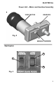
NO. Fig.
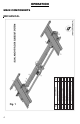
ELECTRICAL Power Unit – Motor and Gearbox Assembly 12VDC MOTOR GEAR BOX Fig. 2 MANUAL OVERRIDE Wall Switch A C B Fig.
OPERATING SYSTEM WARNING FAILURE TO ACT IN ACCORDANCE WITH THE FOLLOWING MAY RESULT IN SERIOUS PERSONAL INJURY OR DEATH. ALWAYS MAKE SURE THAT THE SLIDEOUT ROOM PATH IS CLEAR OF PEOPLE AND OBJECTS BEFORE AND DURING OPERATION OF THE SLIDEOUT ROOM. ALWAYS KEEP AWAY FROM THE SLIDE RAILS WHEN THE ROOM IS BEING OPERATED. THE GEAR ASSEMBLY MAY PINCH OR CATCH ON LOOSE CLOTHING CAUSING PERSONAL INJURY.
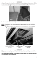
WARNING! Always disconnect battery from system prior to manually operating system. Failure to disconnect battery can cause electricity to backfeed through the motor and cause serious damage to the system as well as void the warranty. Fig. 6 1. Accessing Out-Stop Assembly NOTE: The slideout Out-Stop Assembly will be accesible from the INSIDE of the unit. The Slideout Motor and Mechanism is accessible from the OUTSIDE. MANUAL OVERRIDE Fig.
Fig. 8 Fig. 9 4. With a second person assisting, one person must push and hold the MANUAL OVERRIDE switch (Fig. 3C; pg. 5) in the unit, located on the control panel, while the other person, using a 5/8” wrench or socket/ratchet combination, rotates the hex head MANUAL OVERRIDE (Figs. 8 & 9) to manually move the slideout.
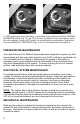
NOTE: For long-term storage: It is recommended that the room be closed (retracted). • • Visually inspect the Slide Floor and Drive Box Assemblies. Refer to Fig. 1 for location of rail assemblies. Check for excess build-up of dirt or other foreign material; remove any debris that may be present. If the system squeaks or makes any noises it is permissible to apply a coat of lightweight oil to the drive shaft and roller areas but remove any excess oil so dirt and debris do not build-up. DO NOT use grease.
TROUBLESHOOTING CHART The folowing troubleshooting chart outlines some common problems, their causes and possible corrective actions. When reference is made to a “Power Unit,” the term includes the motor and the actuator as a complete unit. All Power Units are shipped from the factory with a serial number and date code, which should be given to the service technician when asking for assistance.
TROUBLESHOOTING – MOTOR UNIT Before attempting to troubleshoot the PowerUnit, make sure an adequate power source is available. The unit batteries should be fully charged or the unit should be plugged into to A/C service with batteries installed. Do not attempt to troubleshoot the Power Unit without assuring a full 12V DC charge The following tests require only a DC voltmeter (or DC test light) and a jumper lead.
ROOM ADJUSTMENT HORIZONTAL (SIDE-TO-SIDE) ADJUSTMENT NOT SHOWN VERTICAL (UP AND DOWN) ADJUSTMENT VERTICAL (UP AND DOWN) ADJUSTMENT 1. For Horizontal Adjustment, back both lag bolts out just enough to release tension. In a Dual System, lag bolts must be loosened on both head stocks to adjust the room horizontally. 2. Adjust room to desired location. 3. Tighten lag bolts before operating room. OUT STOP ADJUSTMENT 1. Loosen jam nut (shown) on the outside of the Out Stop Bracket. 2.