ITEM #18032 SAWGRASS CEILING FAN Harbor Breeze® is a registered trademark of LF, LLC. All Rights Reserved. MODEL #E-LUB52BNK5C1S español p. 20 Federal regulations require ceiling fans with light kits manufactured or imported after January 1, 2009, to limit total wattage consumed by the light kit to 190W. Therefore, this fan is equipped with a wattage limiting device.
TABLE OF CONTENTS Safety Information ....................................................................................................................... 2 - 3 Package Contents ........................................................................................................................... 4 Hardware Contents ......................................................................................................................... 5 Preparation ....................................................
SAFETY INFORMATION DANGER If using this fan in a DAMP location, this fan must be connected to a supply circuit that is protected by a Ground Fault Circuit Interrupter (GFCI) to reduce the risk of personal injury, electrical shock or death. WARNINGS To reduce the risk of fire, electrical shock, or personal injury, mount fan to outlet box marked "ACCEPTABLE FOR FAN SUPPORT OF 35 LBS (15.9 KG) OR LESS" and use mounting screws provided with the outlet box.
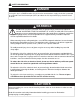
PACKAGE CONTENTS C N A B I D L M E G K U F J P T H W Q O R V S PART A B C D E F G H I J K L DESCRIPTION Downrod Canopy Mounting Bracket Yoke Cover Motor Housing Blade Arm Blade Light Kit Fitter Canopy Cover Motor Screw (preassembled) Lock Washer (preassembled) Pin (preassembled) QUANTITY PART DESCRIPTION QUANTITY 1 1 1 1 1 5 5 1 1 10 M N Clip (preassembled) Canopy Mounting Screw (preassembled) Glass Shade Fitter Plate Threaded Washer (preassembled) Finial Plate (preassembled) Finial (
HARDWARE CONTENTS (shown actual size) AA Blade Screw BB Rubber Blade Washer Qty. 15 CC E3 Wire Connector Qty. 15 Qty. 4 PREPARATION Before beginning assembly of product, make sure all parts are present. Compare parts with package contents list and hardware contents above. If any part is missing or damaged, do not attempt to assemble the product. Contact customer service for replacement parts.
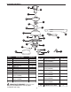
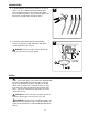
INITIAL INSTALLATION 1. Turn off circuit breakers and wall switch to the fan supply line leads. (Fig. 1) 1 DANGER: Failure to disconnect power supply prior to installation may result in serious injury or death. 2. Determine mounting method to use. (Fig. 2) A. Normal mount B. Angle mount Important: If using the angle mount, check to make sure the ceiling angle is not steeper than 19°. ON ON OFF OFF 2 A B 3. Check to make sure blades (G) are at least 30 in. from any obstruction.
INITIAL INSTALLATION 4. Secure mounting bracket (C) to outlet box using screws, spring washers, and flat washers provided with the outlet box. (Fig. 4) *NOTE: It is very important that you use the proper hardware when installing the mounting bracket (C) as this will support the fan. 4 C IMPORTANT: If using the angle mount, make sure open end of mounting bracket (C) is installed facing the higher point of the ceiling. 5. Remove motor screws (J) and lock washers (K) from underside of motor. (Fig.
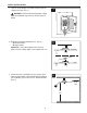
FAN MOUNTING 2. Insert downrod (A) through canopy (B), canopy cover (I) and yoke cover (D). [Note: Canopy cover (I) must be turned with the shiny side toward the motor housing (E).] Thread wires from motor housing (E) through downrod (A). (Fig. 2) 2 A B I D 3. Slip downrod (A) into housing yoke, align holes and re-install pin (L) and clip (M). Tighten downrod (A) set screws and then tighten nuts. Slide yoke cover (D) down until it rests on top of motor housing (E). (Fig. 3) 3 A D M Set Screw L E 4.
FAN MOUNTING 5. If you decided to cut back the lead wires in Step 4, strip 1/2 in. of insulation from end of white wire. Twist stripped ends of each strand of wire within the insulation with pliers. (Fig. 5) Repeat Step 5 for black, blue (if applicable) and green wires. 5 6. Install ball end of downrod (A) into mounting bracket (C) opening. Align slot in ball with tab in mounting bracket (C). (Fig. 6) 6 DANGER: Failure to align slot in ball with tab may result in serious injury or death.
WIRING DANGER: If using this fan in a DAMP location, this fan must be connected to a supply circuit that is protected by a Ground Fault Circuit Interrupter (GFCI) to reduce the risk of personal injury, electrical shock or death. 1. Choose wiring diagram (Fig. 1A, Fig. 1B or Fig.
WIRING 1C. FAN AND LIGHT CONTROLLED BY TWO WALL SWITCHES: If you intend to control the fan and light with separate wall switches, connect BLACK wire from fan to BLACK wire from the independent wall switch for the fan. Connect BLUE wire from fan to the BLACK wire from the other independent wall switch for the light. Connect WHITE wire from fan to WHITE wire from ceiling. Connect all GROUND (GREEN) wires together from fan (on downrod (A) and mounting bracket (C)) to BARE/GREEN wire from ceiling. (Fig.
FINAL INSTALLATION 1. Locate two canopy mounting screws (N) on underside of mounting bracket (C) and remove canopy mounting screw (N) closest to the open end of the mounting bracket (C). Partially loosen the other canopy mounting screw (N). Lift canopy (B) to mounting bracket (C). Place rounded part of slotted hole in canopy (B) over loosened canopy mounting screw (N) in mounting bracket (C) and push up. Twist canopy (B) to lock.
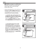
FINAL INSTALLATION 4. Remove one motor plate screw (U) from underside of motor and loosen the other two motor plate screws (U). Align slotted holes in middle of fitter plate (P) with loosened screws in motor plate, allowing male plug from motor housing (E) to come through hole in middle of fitter plate (P). Twist fitter plate (P) to lock. Re-insert motor plate screw (U) that was just removed, and then tighten all three motor plate screws (U) securely. (Fig. 4) 4 E U P Motor Plate Male Plug U 5.
FINAL INSTALLATION 7. Align slotted holes in light kit fitter (H) with loosened screws in fitter plate (P). Re-insert fitter plate screw (T) that was previously removed. Securely tighten all three fitter plate screws (T). (Fig. 7) 7 E T P H T 8. Remove finial (S), finial plate (R) and threaded washer (Q) from light kit fitter (H). (Fig. 8) Save finial (S), finial plate (R) and threaded washer (Q) for later use. 8 E Install three candelabra-base 40-watt max. bulbs (W) provided. (Fig.
FINAL INSTALLATION 10. The pull chain extensions (V) supplied in one of the hardware packs or custom pull chain extensions (not included) may be attached to fan and light pull chains. (Fig. 10) 10 E (For Fan) (For Light) V OPERATION INSTRUCTIONS 1. The pull chain located to one side has four positions to control fan speed. One pull is HIGH, two is MEDIUM, three is LOW and four turns the fan OFF. (Fig. 1) 2. The pull chain located in the middle is used to turn the light ON or OFF. (Fig.
OPERATION INSTRUCTIONS 3. Use the fan reverse switch, located on the fitter plate (P), to optimize your fan for seasonal performance. (Fig. 3) A ceiling fan will allow you to raise your thermostat setting in summer and lower your thermostat setting in winter without feeling a difference in your comfort. 3 P Note: Wait for fan to stop before moving the reverse switch. 3A. In warmer weather, setting the reverse switch in the LEFT position will result in downward airflow creating a wind chill effect. (Fig.
CARE AND MAINTENANCE At least twice each year, lower canopy (B) to check downrod (A) assembly, and then tighten all screws on the fan. Clean motor housing (E) with only a soft brush or lint-free cloth to avoid scratching the finish. Clean blades (G) with a lint-free cloth. You may occasionally apply a light coat of furniture polish to wood blades for added protection. Important: Shut off main power supply before beginning any maintenance. Do not use water or a damp cloth to clean the ceiling fan.
TROUBLESHOOTING PROBLEM POSSIBLE CAUSE CORRECTIVE ACTION Fan operates but light fails. 1. Wires in canopy (B) not wired properly. 1. Check wires in canopy (B) and, if necessary, re-wire according to instructions on pages 10 and 11. 2. Wall switch to fan is off. 2. Make sure that wall switch to fan is on. 3. Small plugs not connected properly. 3. Check that the small male and female plugs in the light kit fitter (H) are connected properly according to instructions on page 13. 4.
REPLACEMENT PARTS LIST For replacement parts, call our customer service department at 1-800-527-1292, 8:30 a.m. - 5:00 p.m., CST, Monday - Friday. When ordering parts, please have the Model # or Item # of the fan available, which can be found on page 1.
ARTÍCULO #18032 VENTILADOR DE TECHO SAWGRASS Harbor Breeze® es una marca registrada de LF, LLC. Todos los derechos reservados. MODELO # E-LUB52BNK5C1S Los reglamentos federales requieren que los ventiladores de techo con kit de iluminación fabricados o importados después del 1 de enero de 2009, tengan un límite de vataje total consumido por el kit de iluminación de 190 vatios. Por lo tanto, este ventilador está equipado con un dispositivo de control de vataje.
ÍNDICE Información de seguridad ....................................................................................................... 21 - 22 Contenido del paquete .................................................................................................................. 23 Aditamentos ................................................................................................................................... 24 Preparación .....................................................................
INFORMACIÓN DE SEGURIDAD PELIGRO Si utiliza este ventilador en un área HÚMEDA, debe conectarlo a un circuito de suministro protegido por un Interruptor de circuito de falla de puesta a tierra (GFCI, por sus siglas en inglés) para disminuir el riesgo de lesiones personales, descargas eléctricas o la muerte. ADVERTENCIAS Para reducir el riesgo de incendios, descargas eléctricas o lesiones personales, monte a una caja de salida marcada como "ACCEPTABLE FOR FAN SUPPORT OF 35 LBS (15.
CONTENIDO DEL PAQUETE C N A B I D L M E G K U F J P T H W Q R O PIEZA A B C D E F G H I J K L DESCRIPCIÓN Varilla Base Abrazadera de montaje Cubierta de la horquilla Carcasa del motor Brazo del aspa Aspa Soporte del kit de iluminación Cubierta de la base Tornillo del motor (preensamblado) Arandela de seguridad (preensamblada) Pasador (preensamblado) V S CANTIDAD PIEZA 1 1 1 1 1 5 5 1 1 10 M N O P Q R S T 10 U 1 RECORDATORIO IMPORTANTE: Debe utilizar las piezas que se incluyen con este
ADITAMENTOS (se muestran en tamaño real) AA BB Tornillo del aspa Arandela de goma para aspa Cant. 15 CC Conector de cables E3 Cant. 15 Cant. 4 PREPARACIÓN Antes de comenzar a ensamblar el producto, asegúrese de tener todas las piezas. Compare las piezas con la lista del contenido del paquete y la lista de aditamentos anteriores. No intente ensamblar el producto si falta alguna pieza o si éstas están dañadas.
INSTALACIÓN INICIAL 1. Interrumpa el suministro de energía del ventilador apagando los interruptores de circuito y el interruptor de pared. (Fig. 1) 1 PELIGRO: Si no interrumpe el suministro de electricidad antes de la instalación, pueden producirse lesiones graves o la muerte. 2. Determine el método de instalación que utilizará. (Fig. 2) A. Montaje normal B. Montaje en ángulo Importante: Si realiza la instalación en ángulo, verifique que el ángulo del techo no tenga una inclinación superior a los 19°.
INSTALACIÓN INICIAL 4. Asegure la abrazadera de montaje (C) a la caja de salida con los tornillos, las arandelas de resorte y las arandelas planas que incluye la caja de salida. (Fig. 4) *NOTA: Es muy importante que use los aditamentos adecuados para instalar la abrazadera de montaje (C), ya que ésta soportará el ventilador. 4 C IMPORTANTE: Si realiza el montaje en ángulo, asegúrese de que el extremo abierto de la abrazadera de montaje (C) esté instalado en dirección hacia el punto más alto del techo.
MONTAJE DEL VENTILADOR 2. Introduzca la varilla (A) a través de la base (B), la cubierta de la base (I) y la cubierta de la horquilla (D). [Nota: La cubierta de la base (I) debe girarse con el lado brillante apuntando hacia la carcasa del motor (E)]. Pase los conductores por la carcasa del motor (E) a través de la varilla (A). (Fig. 2) 2 A B I D 3. Deslice la varilla (A) en la horquilla de la carcasa, alinee los orificios y vuelva a instalar el pasador (L) y el sujetador (M).
MONTAJE DEL VENTILADOR 5. Si decidió cortar los cables conductores en el Paso 4, pele 1,27 cm del aislamiento del extremo del conductor blanco. Tuerza los extremos pelados de cada filamento de conductor dentro del aislamiento con pinzas. (Fig. 5) Repita el paso 5 para los conductores negro, azul (si corresponde) y verde. 5 6. Instale el extremo con la bola de la varilla (A) en la abertura de la abrazadera de montaje (C). Alinee la ranura de la bola con la lengüeta en la abrazadera de montaje (C). (Fig.
CABLEADO PELIGRO: Si utiliza este ventilador en un área HÚMEDA, debe conectarlo a un circuito de suministro protegido por un Interruptor de circuito de falla de puesta a tierra (GFCI, por sus siglas en inglés) para disminuir el riesgo de lesiones personales, descargas eléctricas o la muerte. 1. Escoja el diagrama de cableado (Fig. 1A, Fig. 1B o Fig.
CABLEADO 1C. VENTILADOR Y LUZ CONTROLADOS POR DOS INTERRUPTORES DE PARED: Si desea controlar el ventilador y la luz con interruptores de pared separados, conecte el conductor NEGRO del ventilador al conductor NEGRO del interruptor de pared independiente para el ventilador. Conecte el conductor AZUL del ventilador al conductor NEGRO del otro interruptor de pared independiente para la luz. Conecte el conductor BLANCO del ventilador al conductor BLANCO del techo.
INSTALACIÓN FINAL 1. Ubique dos tornillos de montaje de la base (N) debajo de la abrazadera de montaje (C) y retire el tornillo de montaje de la base (N) más cercano al extremo abierto de la abrazadera de montaje (C). Afloje parcialmente el otro tornillo de montaje de la base (N). Levante la base (B) hasta la abrazadera de montaje (C). Coloque la parte redondeada del orificio ranurado de la base (B) sobre el tornillo de montaje de la base (N) suelto en la abrazadera de montaje (C) y empuje hacia arriba.
INSTALACIÓN FINAL 4. Retire un tornillo de la placa del motor (U) de la parte inferior del motor y afloje los otros dos tornillos de la placa del motor (U). Alinee los orificios ranurados en el centro de la placa de soporte (P) con los tornillos aflojados en la placa del motor, permitiendo que el conector macho de la carcasa del motor (E) pase por el orificio en el centro de la placa de soporte (P). Gire la placa de soporte (P) para bloquearla.
INSTALACIÓN FINAL 7. Alinee los orificios ranurados del soporte del kit de iluminación (H) con los tornillos sueltos de la placa de soporte (P). Vuelva a insertar el tornillo de la placa de soporte (T) que retiró anteriormente. Apriete firmemente los tres tornillos de la placa de soporte (T). (Fig. 7) 7 E T P H 8. Retire el remate (S), la placa del remate (R) y la arandela roscada (Q) del soporte del kit de iluminación (H). (Fig.
INSTALACIÓN FINAL 10. Las extensiones para la cadena de tiro (V) que se suministran en uno de los paquetes de aditamentos o las extensiones para las cadenas de tiro a medida (no se incluyen) se pueden fijar a las cadenas de tiro del ventilador y la luz. (Fig. 10) 10 E (para el ventilador) (para la luz) V INSTRUCCIONES DE FUNCIONAMIENTO 1. La cadena de tiro ubicada a un lado tiene cuatro posiciones para controlar la velocidad del ventilador.
INSTRUCCIONES DE FUNCIONAMIENTO 3. Utilice el interruptor de reversa del ventilador, ubicado en la placa de soporte (P), para optimizar el rendimiento de su ventilador según la estación del año. (Fig. 3) Un ventilador de techo le permitirá elevar la configuración de su termostato en verano y disminuirla en invierno, sin sentir una diferencia en su comodidad. 3 P Nota: Espere a que el ventilador se detenga antes de mover el interruptor de reversa. 3A.
CUIDADO Y MANTENIMIENTO Al menos dos veces al año, baje la base (B) para revisar en ensamble de la varilla (A) y luego apriete todos los tornillos en el ventilador. Limpie la carcasa del motor (E) sólo con un cepillo suave o un paño que no produzca pelusas para evitar rayar el acabado. Limpie las aspas (G) con un paño que no produzca pelusas. De vez en cuando puede aplicar una fina capa de cera para muebles en las aspas de madera para darles más protección.
SOLUCIÓN DE PROBLEMAS PROBLEMA CAUSA POSIBLE ACCIÓN CORRECTIVA El ventilador funciona pero la luz no. 1. Los conductores de la base (B) no están bien conectados. 1. Revise los conductores de la base (B) y, si es necesario, vuelva a conectarlos de acuerdo con las instrucciones de las páginas 29 y 30. 2. Asegúrese de que el interruptor de pared del ventilador esté en la posición de encendido. 3.
LISTA DE PIEZAS DE REPUESTO Para obtener piezas de repuesto, llame a nuestro Departamento de Servicio al Cliente al 1-800-527-1292, de lunes a viernes de 8:30 a.m. a 5:00 p.m., hora central estándar. Cuando pida piezas, tenga a mano el # de modelo o # de artículo del ventilador, los que aparecen en la página 20.