
Installation Guide


10
WIRING
DANGER: If using this fan in a DAMP location,
this fan must be connected to a supply circuit that is
protected by a Ground Fault Circuit Interrupter
(GFCI) to reduce the risk of personal injury,
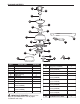
electrical shock or death.
1A
FAN AND LIGHT CONTROLLED BY PULL CHAINS
BLACK
WHITE
GROUND/GREEN (BARE)
WHITE
BLUE
WHITE
FROM FAN
120 V Power
FROM
CEILING
FAN
GREEN
BLACK
GREEN
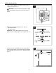
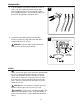
Choose wiring diagram (Fig. 1A, Fig. 1B or Fig. 1C)
that fits your situation and make appropriate wiring
connections as follows: [NOTE: For each wire
connection below, use one of the wire connectors
(CC) provided, making sure to screw wire
connector (CC) on in a clockwise direction.]
1A. FAN AND LIGHT CONTROLLED BY PULL
CHAINS: Connect BLACK and BLUE wire from
fan to BLACK wire from ceiling. Connect WHITE
wire from fan to WHITE wire from ceiling.
Connect all GROUND (GREEN) wires together
from fan (on downrod (A) and mounting bracket
(C)) to BARE/GREEN wire from ceiling. (Fig. 1A)
1.
WHITE
BLACK
BLACK (WALL SWITCH)
GROUND/GREEN (BARE)
BLACK
BLUE
WHITE
FROM FAN
FAN
120 V Power
FROM
CEILING
GREEN
WHITE
GREEN
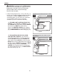
1B
FAN CONTROLLED BY PULL CHAIN, LIGHT BY
WALL SWITCH
1B. FAN CONTROLLED BY PULL CHAIN,
LIGHT BY WALL SWITCH: If you intend to
control the fan light with a separate wall switch,
connect BLACK wire from fan to BLACK wire
from ceiling. Connect BLUE wire from fan to the
BLACK wire from the independent wall switch for
the light. Connect WHITE wire from fan to WHITE
wire from ceiling. Connect all GROUND
(GREEN) wires together from fan (on downrod
(A) and mounting bracket (C)) to BARE/GREEN
wire from ceiling. (Fig. 1B)