
Technical Specifications

900 Northrop Road, Wallingford, CT 06492 • 1.800.PASSIVE • FX 203.269.9621 • www.sensorswitch.com
WARRANTY: Sensor Switch, Inc. warrants these products to be free of defects in manufacture and workmanship for a
period of 60 months. Sensor Switch, Inc., upon prompt notice of such defect, will, at its option, provide a Returned Material
Authorization number and repair or replace returned product.
LIMITATIONS AND EXCLUSIONS: This Warranty is in full lieu of all other representation and expressed and implied
warranties (including the implied warranties of merchantability and tness for use) and under no circumstances shall
Sensor Switch, Inc. be liable for any incidental or consequential property damages or losses.
TS-CMRB-013A
Revised 07.14.10 ©2010 Sensor Switch
INSTALLATION
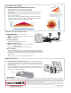
WIRING (DO NOT WIRE HOT)
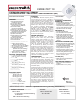
COVERAGE PATTERN
PROGRAMMING
Refer to instruction card IC7.001 for default settings and directions on programming the sensor via the push-button.
FB3
10 EXTENDED RANGE 360º LENS WITH MICROPHONICS™
0
ft
9
0 m
2.7
28 21 14 7 0 ft 7 14 21 28
8.5 6.4 4.3 2.1 0 m 2.1 4.3 6.4 8.5
SIDE VIEW
TOP VIEW
28
14
0
ft
14
28
8.5
4.3
0
m
4.3
8.5
0
ft
9
0 m
2.7
28 21 14 7 0 ft 7 14 21 28
8.5 6.4 4.3 2.1 0 m 2.1 4.3 6.4 8.5
SIDE VIEW
TOP VIEW
28
14
0
ft
14
28
8.5
4.3
0
m
4.3
8.5
*At 9ft Mtg.
• Best choice for large motion detection (e.g. walking)
• Viewing angle of 67º in a 360º conical shaped pattern
• Provides 28 ft (8.53 m) radial coverage when mounted to standard 9 ft
(2.74 m) ceiling
• 7 to 15 ft (2.13 to 4.57 m) mounting heights provide 16 to 36 ft (4.88 to
10.97 m) radial coverage
• Microphonics™ provides overlapping detection of human activity over
the complete PIR coverage area. Advanced ltering is also utilized to
prevent non-occupant noises from keeping the lights on.
A: When walking across beam, detection
will occur at approximately 28 ft (8.53 m)
B: When walking into beam, detection will
occur at approximately 24 ft (7.32 m)
VIO (+)
GRY (-)
[D, ADC] Automatic Dimming
Control
STANDARD WIRING
BLACK* - Line Input
BLACK* - Load Output
WHITE - Neutral
347 VAC OPTION (347)
Black wires are replaced w/ Red wires
DIMMING OPTIONS (D, ADC)
VIOLET - Connect to Violet control wire from 0-10 VDC
dimmable ballast
GRAY - Connect to Gray common wire from ballast
INITIAL POWER UP
The sensor’s relay is shipped in a latched closed position so the lights will
come on upon initial power-up. If the lights do not immediately turn on (initial
installation only) the latching relay opened during shipment and will close
within 30 secs.
Note: If the sensor loses power, the internal relay will latch to on.
• The Fixture Mount Box enclosure has an extended chase nipple that is used
to mount the sensor through a ½” knockout hole to a xture or junction box.
• Sensor will detect motions crossing segments more effectively than motions
parallel to beams.
• If the sensor’s eld-of-view is partially blocked by the xture housing, the
FB3 Fixture Bracket (not included) can be used to lower the sensor down to
a level where its view is not impaired.
PUSH BUTTON
LOCK NUTCHASE NIPPLE KNOCK OUT
*BLACK wires can be reversed
}