
Installation Guide


INSTALLATION INSTRUCTIONS - ENGLISH
INSTALLATION INSTRUCTIONS
Page 5
Page 4
Page 2
1. Remove Diffuser (5) by pivoting Diffuser Latches (4)
outward (away) from Housing Assembly (1).Remove parts
pack(s). Check that all parts are included. See Fixture
Packing List on Page 2.
NOTE:
Turn off power at fuse or circuit breaker box!
2. Install Crossbar (7) to junction box with two 1" Screws (2).
Install Threaded Rod (8) into Crossbar (7). Leave approx.
7/8”
threaded rod exposed. Tighten locknut (11).
3. Check that black, white and green wires are extending
from the the back of the fixture.
WIRING AND FIXTURE OPERATION CAUTION:
Connect fixture to supply wires rated for at least 90°C
(194°F).
Note: Assistance may be required to support fixture during
installation.
4. With the power turned off, hold the fixture Housing
Assembly (1) firmly and connect the green ground wire
from the fixture to the bare copper ground wire from the
junction box using a Wirenut (3). (If house wiring does not
include a ground wire, consult your local electrical code for
approved grounding methods). See Fig. 1.
FOR PROPER CONNECTION, PLACE WIRENUT OVER
WIRES, TWIST CLOCKWISE UNTIL TIGHT.
5. Use Wirenuts (3) to connect black fixture wire to the black
power supply wire and white fixture wire to the white power
supply wire. See Fig. 1.
6. Hold Housing Assembly (1) in one hand and with the other
hand position wires up and into outlet box.
7. Align Threaded Rod (8) with center hole on Housing. Push
Housing Assembly (1) to ceiling surface. Install Washer
(9) onto Rod (8) and secure fixture with Cap Nut (10).
Note: Cap nut (10) should be hand-tighten only. Do not over
tighten.
WARNING: RISK OF SHOCK- Do not operate fixture without
Barrier Lens (6) installed.
8. To install Diffuser (5)- position diffuser flange inside
Housing Assembly (1), pivot Diffuser Latches (4) inward to
captivate Diffuser (5).
9. Turn on electricity at fuse or circuit breaker box and
verify success of installation.
1. Retire el difusor (5) girando los pestillos del difusor (4)
hacia afuera (lejos) del conjunto de la carcasa (1). Retire
los paquetes de piezas. Verifique que no falten piezas.
Consulte la Lista de empaque de montaje en la página 2.
Nota: ¡Apague la electricidad en la caja de cortacircuitos o de
fusibles!
2. . Instale la barra transversal (7) a la caja de unión con dos
tornillos 1" (2). Instale la vara roscada (8) en la barra
transversal (7). Deje aproximadamente 7/8" de la vara
roscada al descubierto. Ajuste la contratuerca (11).
3. Revise que los almabres negro, blanco y verde esten
extendidos desde la parte trasera de la luminaria. Remueva
el plástico del difusor que lo sujeta a la luminaria.
CUIDADO DE LA OPERACIÓN DEL LUMINARIO Y EL
ALAMBRADO: Conecte el luminario a alambres de
suministros que estén clasificados a por lo menos 90°C
(194° F).
Nota: Puede que necesite asistencia para sostener el luminario
durante la instalación.
4. Con la electricidad apagada, sostenga la Ensamblaje de
la carcasa (1) firmemente y conecte el alambre verde de
conexión a tierra del luminario al alambre desnudo de
cobre de la caja de ensambladura usando un capuchón de
alambres (3). (Si el alambrado de la casa no incluye un
alambre de hacer tierra, consulte su código eléctrico local
para métodos aprobados de hacer tierra. Vea Fig. 1.
PARA UNA CONEXIÓN APROPIADA, COLOQUE EL
CAPUCHÓN DE ALAMBRES SOBRE LOS ALAMBRES, GIRE
HACIA SU DERECHA HASTA QUE QUEDE APRETADO.
5. Use Capuchones de Alambres (3) para conectar el alambre
negro del luminario al alambre negro de suministro eléctrico y
el alambre blanco del luminario al alambre blanco de
suministro eléctrico. Vea Fig. 1.
6. Sostenga el Ensamblaje de la Carcasa (1) con una mano y\
con la otra estire los cables dentro del la caja de conexiones.
7. Alinee la vara roscada (8) con el orificio central en la carcasa.
Empuje el conjunto de la carcasa (1) a la superficie del techo.
Instale la arandela (9) en la vara (8) y asegure el montaje con
la tuerca ciega (10).
Nota: La tuerca ciega (10) solo debe ser ajustada manualmente.
No ajuste excesivamente.
ADVERTENCIA: RIESGO DE ELECTROCHOQUE. No utilice el
dispositivo si las lentes de barrera (6) no están instaladas.
8.
Para instalar el difusor (5) coloque el reborde del difusor
dentro del conjunto de la carcasa (1), gire los pestillos del
difusor (4) hacia adentro del difusor (5).
9. Encienda la electricidad en la caja de fusibles o caja
de cortacircuitos y verifique el éxito de la instalación.
GUÍA DE PASO-A-PASO
LISTE DES PIECES
Quincaillerie de Montage
Incluses
LISTA DE EMBALAJE
Herraje para Montaje
Incluidas
REQUIRED TOOLS
HERRAMIENTAS REQUERIDAS
OUTILS REQUIS
INSTALLATION FIGURES
FIGURES D’INSTALLATION
FIGURAS DE LA INSTALACIÓN
Guía de Localización de Averías
Si este luminario falla de operar apropiadamente, use la
siguiente guía para diagnosticar y corregir el problema.
Verifique que el luminario este alambrado apropiadamente.
Verifique que el luminario este conectado tierra
correctamente.
El voltaje de la línea en el luminario este correcto
Si requere ayuda adicional, contacte:
Technical Support: (800) 748-5070.
Esta lámpara LED con detector de movimiento necesita
muy poco mantenimiento y no es necesario cambiar los
focos.
COMO LIMPIAR EL ACRILICO: Para mayor resultado,
difusor de acrilico se debe lavar con jabon o detergents
suaves. Enjuague con agua y deje secar al aire.
Reductores de alumbrado recomendados
Este montaje se diseñó para operar con la mayoría de los
reductores de alumbrado con triac estándares (control de fase
directa o borde de ataque) y no es compatible con los sistemas
de reducción de luz de entre 0 y 10 v.A continuación se enumera
una serie de reductores de alumbrado que han sido probados
con este montaje. No se garantiza la compatibilidad de este
listado de reductores de alumbrado con ninguna aplicación en
particular.Los reductores de alumbrado que no se incluyen en la
lista no son necesariamente incompatibles.
Lutron: DVELV 300P, Skylark 300P, NTELV 300, NLV 600
Leviton: 6633P, IPL06, 6674P, IPE04, Tramatron 600W
Synergy: ISD 600 I 120
Trouble Shooting Guide
If this fixture fails to operate properly, use the guide below
to diagnose and correct the problem.
Verify that fixture is wired properly.
Verify that fixture is grounded correctly.
The line voltage at the fixture is correct.
If further assistance is required, contact:
Technical Support at: (800) 748-5070
This LED light provides low maintenance service with no
bulbs to change.
Cleaning Diffuser: For best results, diffusers should be
washed with soap or mild detergent. Rinse with clear wa-
ter and allow to air dry.
Description Quantité
1) Bloc boîtier ............................................... 1
2) Vis* ........................................................... 2
3) Capuchons de connexion*...................... 3
4) Fermoir du diffuseur ................................ 3
5) Diffuseur................................................... 1
6) Lentille Barrière ........................................ 1
7)
Barre transversale* ......................... 1
8) Tige filetée*...................................... 1
9) Rondelle* ........................................ 1
10) L’écrou borgne* .............................. 1
11) Contre-écrou* ................................ 1
*Contained in Part Packs
Descripción Cantidad
1) Ensamblaje de la Carcasa ...................... 1
2) Tornillos* ................................................... 2
3) Capuchones de Alambres* ..................... 3
4) Aldaba del Difusor ................................... 3
5)Difusor ...................................................... 1
6) Lentes de barrera.................................... 1
7) Barra transversal*................................... 1
8) Vara roscada* .......................................... 1
9)
Arandela* ........................................ 1
10) Tuerca ciega* .................................. 1
11)
Contratuerca* ........................................ 1
*Contained in Part Packs
Suggested Dimmers
This fixture is designed to operate with most standard Triac Based
(Forward Phase-Control or Leading Edge) dimmer and is not
compatible with 0-10v dimming systems.
Noted below is a listed of dimmers that have been tested with this
fixture. This list of dimmers does not imply any guarantee or
warranty of compatibility with a particular application.
Dimmers that are not listed do not imply non-compatibility.
Lutron: DVELV 300P, Skylark 300P, NTELV 300, NLV 600
Leviton: 6633P, IPL06, 6674P, IPE04, Tramatron 600W
Synergy: ISD 600 I 120
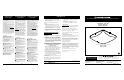
Figure 1
1) Housing Assembly
3) Wire Nut
4) Diffuser Latch
5) Diffuser
6) Barrier Lens
2) 1” Screw
7) Cross Bar
8) Threaded Pipe
9) Washer
10) Cap Nut
Description Quantity
FIXTURE PARTS LIST
FIXTURE PARTS LIST
1) Housing Assembly .................................. 1
2)Screws* .................................................... 2
3) Wire Nuts* ................................................3
4) Diffuser Latch .......................................... 3
5)Diffuser..................................................... 1
6) Barrier Lens .............................................1
7) Crossbar* ................................................ 1
8) Threaded Rod* ........................................ 1
9) Washer* ................................................... 1
10) Cap Nut* ................................................. 1
11) Locknut*.................................................. 1
*Contained in Part Packs
Mounting Hardware
Included
11) Locknut