
Installation Guide

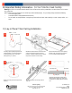

C) Lay-in Panel T-bar Ceiling Installation (Cont.)
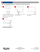
7
8
Re-tighten both vertical adjustment nuts.
9
Re-tighten both channel bar clamping
screws.
CJ5201053 Rev. D
Page 4
© Acuity Brands Lighting, Inc. 2016
All Rights Reserved.
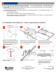
10
Remove knockouts on junction box to feed
power supply to fixture. Supply wire must
meet applicable electrical codes and be
rated for a minimum of 90°C. Junction box
is thru-wire rated for 8-No. 12 AWG
conductors (4in-4out).
11
Complete necessary splices. Snap the
door/driver assembly onto the junction
box.
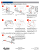
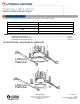
1
Mount to joists with flanges on channel
bars resting against the bottom faces of
the joists. Drive included nail into joist to
secure. Move vertical adjustment to
lowest point. For WALLWASH applications,
ensure the junction box is oriented either
directly toward or away from the washed
wall. Trim rotates only in 180
0
.
12
Squeeze wire springs on the light engine
and insert each leg of the spring into the
slots on the brackets on either side of the
opening in the mounting frame. Pull the
light engine down so the looped end of the
wire spring rests on the top of the bracket.
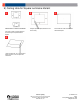
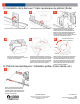
Hole
Tab on Light Engine
D) Non-accessible Ceiling Installation (e.g. plaster, drywall, etc.)
Lithonia Lighting
1400 Lester Road Conyers Georgia 30012
P 800 315 4935 F 770 860 3129
www.Lithonia.com
Trim Slot
Align the opening in the trim with the tabs
on the light engine. Rotate the trim
clockwise until trim slot aligns with the
hole in the trim holder. Secure trim with
provided screw. Push the light engine up
so it flush with the ceiling.