
Installation Guide

Page 3 of 4
LED
Little Wall Pack | Pequeña Luz de Pared | Petite Applique
TOOLS REQUIRED FOR INSTALLATION
(not included)
/ HERRAMIENTAS NECESSARIAS PARA LA
INSTALACIÓN
(no incluidas)
/ OUTILS REQUIS POUR L’INSTALLATION
(non inclus)
Ladder
/ Escalera
/ Échelle
Safety Glasses
/ Gafas de seguridad
/ Lunettes de protection
Gloves
/ Guantes
/ Gants
Silicone Sealant
/ Sellador de silicona
/ Agent d’étanchéité à base de silicone
Phillips Screwdriver
/ Destornillador Phillips
/ Tournevis Phillips
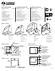
3. Run the supply wires through the center hole in the back
plate (Figure 2) and secure the back plate to the junction
box using the provided screws and the slots in the back
plate. Use the open slots that best t the junction box.
Note: When using electrical conduit for supply wires (instead of junction
box), connect the conduit directly to the back plate center hole or conduit
entry ports (on EL and BB Models). The center hole and conduit entry
ports are set up to accept ½” electrical conduit. Then secure back plate
to the wall using wall anchors (not included).
4. Connect xture leads to junction box leads (Figure 3).
Note for EL Models: Power to the battery needs to be supplied using
an un-switched power source (Figure 3). Power for regular illumination
can be either switched or un-switched as needed.
a. Connect ground wire (green) from xture to grounding
conductor of supply circuit and secure with wire nut. For
proper wire connections, place wire nut over wires and
twist clockwise until tight.
b. Connect neutral wire (white) from xture to neutral wire of
supply circuit and secure with wire nut.
c. Connect hot wire (black) wire from xture to hot wire of
supply circuit and secure with a wire nut.
d. For EL Models: Connect the battery leads for battery
backup function to be activated.
Note: Always connect the green ground wire rst. Individually cap any unused
wires. Use UL listed wire connectors suitable for the size, type, and number of
conductors. No loose strands or loose connections should be present.
STEP 3: INSTALL HOUSING
1. Close the xture by “hanging” the front housing to the back
plate with the two tabs on the back plate (Figure 2). Then
push the housing towards the back plate and tighten screw
at the bottom of the xture.
Note: Ensure no wires are pinched before tightening. Do not to over-
tighten the screw.
2. Apply caulking to the perimeter of the xture between the
housing and the wall (top and two sides) leaving the bottom
side clear of any caulking (Figure 4). Caulking will prevent
any water coming down the wall from entering the xture.
STEP 4: RESTORE POWER
1. Restore power at the main fuse or circuit breaker box.
2. Check operation of xture.
Note for PE Models: Test xture at night or block Photocell to turn
xture on. Cover the photo sensor with electrical tape, then turn power
on and allow a couple of minutes for the sensor to activate the xture.
Then remove the electrical tape and the xture will start to operate
automatically when the ambient light is low enough.
Note for EL Models: When power is supplied to the battery the test button
will light up indicating the battery is charging. Allow the battery to charge for at
least 24 hours, then perform a short test by pushing the test button. The xture
will switch to battery mode and deliver about half the normal illumination. After
the battery is fully charged (at least 48 hours of continuous power) a full 90
minute test can be performed by cutting power to the xture.
SAVE THESE INSTRUCTIONS: Protect yourself. Before
installing, read the entire instructions carefully and save them
for future reference.
DATE INSTALLED: __________________________________
READ AND FOLLOW ALL SAFETY INSTRUCTIONS
WARNING: When using electrical equipment, basic
safety precautions should always be used including the
following: This product must be installed in accordance
with the applicable installation code by a person familiar
with the construction and operation of the product and the
hazards involved. Neutral wire is required for three phase
input.
CAUTION - Regarding EL Models:
• Battery is rechargeable Ni-Cd type and must be recycled
or disposed of properly. Do not use this battery driver
with accessory equipment other than recommended by
manufacturer; failure to follow this may cause an unsafe
condition.
• Do not use battery driver for other than intended use. Not
suitable for high-risk task area lighting.
• Equipment should be mounted in locations and
at heights where it will not readily be subjected to
tampering by unauthorized personnel.
• Do not mount near gas or electric heaters.
STEP 1: PREPARE FOR INSTALLATION
1. Disconnect Power. AC power must be off before proceeding
with assembly or installation. Always disconnect power
during installation or maintenance. Ensure the power is OFF
and disconnected by turning off the circuit breaker or by
removing the appropriate fuse at the fuse box.
2. Before installation, ensure the input power is 120-277VAC,
60Hz and supply wires are rated for at least 90°C (194°F).
3. Review installation diagrams (Figures 1-4).
4. Carefully remove xture components and parts pack
included for assembly. Check to ensure all parts are
included. Account for small parts and destroy packing
material, as these may be hazardous to children.
5. Gather required tools.
CAUTION: Do not rely on wall switch alone to turn off power. Turning the
power off to the light switch alone is not sufcient to prevent electrical
shock.
STEP 2: ELECTRICAL CONNECTIONS
Note: Assistance may be required to support xture during installation.
1. Pull out the supply wires and house grounding wire from the
junction box.
2. Open the xture by loosening the bottom screw (Figure 2).
This separates the front housing from the back plate.
Note if installing with BB Model: Remove back plate from Conduit
Entry Wiring Box, install silicon gasket to groove, then install Wiring Box
to standard or PE models using screws provided.
PRODUCT MAINTENANCE
1. Turn off power to xture. Be sure xture temperature is
cool enough to touch. Do not clean or maintain while xture is
energized.
2. Dust xture with a clean and soft, dry cloth.
3. Wipe xture clean with a damp cloth as needed. Do not use
any cleaners with harsh chemicals, solvents, or abrasives. Do
not use abrasive materials such as scouring pads or powders,
steel wool or abrasive paper.
4. Allow xture to dry completely before power is restored.
Note: There are no user serviceable parts inside xture. Do not touch LED’s.
Note for EL Models: It is recommended and required by applicable
code to test battery ballast to ensure proper function of the system. Push
the test switch for thirty (30) seconds every thirty (30) days to ensure
the battery driver is functioning by illuminating the light source. Conduct
a ninety (90) minutes discharge test one (1) time per year; LED light
source should be illuminated for a minimum of ninety (90) minutes .
LISTINGS: UL certied to US and Canadian safety standards;
Wet location listed (wall mount only).
5-YEAR LIMITED WARRANTY: Failure to follow any of these
instructions could void product warranties. For a complete
listing of product Terms and Conditions, please visit
www.acuitybrands.com. Acuity Brands Lighting, Inc. assumes
no responsibilities for claims arising out of improper or careless
installation or handling of its products.
TROUBLESHOOTING GUIDE
Problem: Corrective Action:
Fixture will not
illuminate.
1. Verify photocell is working properly by covering
it to block light from entering (light should turn on)
(PE Models Only).
2. Verify line voltage is correct.
3. Check wiring and connections.
4. Verify power supply is on at switch and
breaker.
5. Test or replace switch.
Fixture will not
turn off.
Verify photocell is working properly by shining a
ashlight into it (light should turn off) (PE Models
Only).
Circuit breaker
trips when
xture is
illuminated.
Check wire connections. Ensure wires are not
crossed and power wire is not grounding out.
Consult electrician.
Light ickering
or light is
cycling on and
off.
1. Eliminate reective surfaces or reposition
xture.
2. Check wiring and connections.
3. Test or replace switch.
4. Consult electrician.
If further assistance is required, contact:
Technical Support at: (800) 748-5070
INSTALLATION INSTRUCTIONS