
Installation Guide

page 3
INSTALLATION INSTRUCTIONS
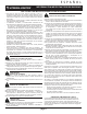
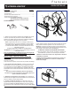
5. Aim lamp head. Each lamphead can be positioned in multiple
directions via the adjustment screw in the elbow and the lock nut
(3). See Fig B.
Note: Make sure to secure lock nut and adjustment screw tightly
after nal adjustments are made to avoid water entry.
CAUTION - Risk of Shock: Aim lamp heads at least 20° down
below horizontal in order to prevent water from accumulating
inside lens.
6. Turn on electricity at fuse or circuit breaker box and verify
success of installation.
7. Apply silicone caulking (not included) around the
perimeter of the xture back where it contacts the mounting
surface for moisture seal!
1. Remove xture components and parts pack. Check to
ensure all parts are included. Note: Account for small parts and
destroy packing material, as these may be hazardous to children.
Note: Suitable for wall mount or eave mount. Not suitable for
ground mount installation. Not suitable for use with dimmers,
motion sensors or other remote devices.
Turn OFF Power at circuit breaker box.
CAUTION: Do not rely on wall switch alone to turn o power
For installation to properly installed and grounded UL listed
junction box
CAUTION: WIRING AND FIXTURE OPERATION
Connect xture to supply wires rated for at least 90°C (194°F).
Make sure power is turned o. Connect to 120V, 60Hz circuit only.
2. Ground xture using wire nut (5) to connect the (copper)
house supply ground wire & the green xture ground wire. Note:
If house wiring does not include a ground wire, consult your local
electrical code for approved grounding methods.
For proper connection, place wire nut over wires
and twist clockwise until tight.
3. Connect supply wires using wire nut (5) to connect the black
xture wire to the black power supply wire and the white xture
wire to the white (neutral) supply wire.
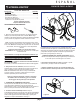
4. Center Mounting Plate over junction box aligning holes in
junction box with holes in Mounting Plate. Insert 3/4” Screws (4)
into holes in Mounting Plate and tighten to secure to junction box.
See Fig A.
Note: make sure no wires are pinched before tightening screws.
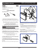
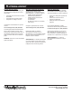
FIXTURE PACKING LIST
Description Quantity
1) LED Light Fixture................................................................. 1
2) Mounting Plate .................................................................... 1
3) Lock Nut .............................................................................. 1
4) 3/4” #8-32 & #10-24 Mounting Screws* .............................. 4
5) Wire Nuts* ........................................................................... 3
*Contained in parts packs
Mounting Hardware Included
Silicone Sealant Required
REQUIRED TOOLS:
Figure A
1) LED Light Fixture
4) 3/4” Screws
5) Wire Nuts
1
1
2
2
3
3
4
4
A A
B B
C C
D D
SHEET
1
OF
1
DRAWN
CHECKED
QA
MFG
APPROVED
BBT01
11/22/2016
DWG NO
TITLE
SIZE
C
SCALE
REV
3) Lock Nut
Figure B
2) Mounting Plate