
Brochure

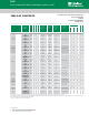
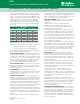
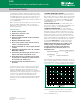
Table Of Contents

© 2017 Littelfuse, Inc.
Specifications are subject to change without notice.
Revised: 03/03/17
FUSE
Circuit Protection Products and Mounting Accessories
length or diameter dimensions of the glass fuses. Their
designation was modified to AB in place of AG, indicating
that the outer tube was constructed from Bakelite, fibre,
ceramic, or a similar material other than glass. The largest
size fuse shown in the chart is the 5AG, or “MIDGET,”
a name adopted from its use by the electrical industry
and the National Electrical Code range which normally
recognizes fuses of 9/16”× 2” as the smallest standard
fuse in use.
FUSE SIZES
SIZE DIAMETER (Inches) LENGTH (Inches)
1AG
1/4
.250
5/8
.625
2AG – .177 – .588
3AG
1/4
.250 1¼ 1.25
4AG
9/32
.281 1¼ 1.25
5AG
13/32
.406 1½ 1.50
7AG
1/4
.250
7⁄8
.875
8AG
1/4
.250 1 1
TOLERANCES: The dimensions shown in this catalog
are nominal. Unless otherwise specified, tolerances are
applied as follows. Tolerances do not apply to lead lengths:
± .010” for dimensions to 2 decimal places.
± .005” for dimensions to 3 decimal places.
Contact Littelfuse should you have questions regarding
metric system and fractional tolerances.
FUSE CHARACTERISTICS: This characteristic of a fuse
design refers to how rapidly it responds to various current
overloads. Fuse characteristics can be classified into three
general categories: very fast-acting, fast-acting, or Slo-Blo
®
Fuse. The distinguishing feature of Slo-Blo
®
fuses is that
these fuses have additional thermal inertia designed to
tolerate normal initial or start-up overload pulses.
FUSE CONSTRUCTION: Internal construction may vary
depending on ampere rating. Fuse photos in this catalog
show typical construction of a particular ampere rating
within the fuse series.
FUSEHOLDERS: In many applications, fuses are
installed in fuseholders. These fuses and their associated
fuseholders are not intended for operation as a “switch”
for turning power “on” and “off “.
INTERRUPTING RATING: Also known as breaking
capacity or short circuit rating, the interrupting rating is
the maximum approved current which the fuse can safely
interrupt at rated voltage. During a fault or short circuit
condition, a fuse may receive an instantaneous overload
current many times greater than its normal operating
current. Safe operation requires that the fuse remain intact
(no explosion or body rupture) and clear the circuit.
Interrupting ratings may vary with fuse design and range
from 35 amperes for some 250VAC metric size (5×20mm)
fuses up to 200,000 amperes for the 600VAC KLK series.
Information on other fuse series can be obtained from the
Littelfuse
Fuses listed in accordance with UL/CSA/ANCE 248 are
required to have an interrupting rating of 10,000 amperes
at 125V, with some exceptions (See STANDARDS section)
which, in many applications, provides a safety factor far in
excess of the short circuit currents available.
NUISANCE OPENING: Nuisance opening is most often
caused by an incomplete analysis of the circuit under
consideration.
Of all the “Selection Factors” listed in the FUSE
SELECTION GUIDE, special attention must be given
to items 1, 3, and 6, namely, normal operating current,
ambient temperature, and pulses.
For example, one prevalent cause of nuisance opening in
conventional power supplies is the failure to adequately
consider the fuse’s nominal melting I
2
t rating. The fuse
cannot be selected solely on the basis of normal operating
current and ambient temperature. In this application, the
fuse’s nominal melting I
2
t rating must also meet the inrush
current requirements created by the input capacitor of the
power supply’s smoothing filter.
The procedure for converting various waveforms into I
2
t
circuit demand is given in the FUSE SELECTION GUIDE.
For trouble-free, long-life fuse protection, it is good design
practice to select a fuse such that the I
2
t of the waveform
is no more than 20% of the nominal melting I
2
t rating of
the fuse. Refer to the section on PULSES in the FUSE
SELECTION GUIDE.
RESISTANCE: The resistance of a fuse is usually an
insignificant part of the total circuit resistance. Since the
resistance of fractional amperage fuses can be several
ohms, this fact should be considered when using them
in low-voltage circuits. Actual values can be obtained by
contacting Littelfuse.
Most fuses are manufactured from materials which have
positive temperature coefficients, and, therefore, it is
common to refer to cold resistance and hot resistance
(voltage drop at rated current), with actual operation being
somewhere in between.
Cold resistance is the resistance obtained using a
measuring current of no more than 10% of the fuse’s
nominal rated current. Values shown in this publication for
cold resistance are nominal and representative. The factory
should be consulted if this parameter is critical to the
design analysis.
Hot resistance is the resistance calculated from the
stabilized voltage drop across the fuse, with current equal
to the nominal rated current flowing through it. Resistance
data on all Littelfuse products are available on request.
Fuses can be supplied to specified controlled resistance
tolerances at additional cost.
SOLDERING RECOMMENDATIONS: Since most fuse
constructions incorporate soldered connections, caution
should be used when installing those fuses intended to
be soldered in place. The application of excessive heat can
reflow the solder within the fuse and change its rating.
Fuses are heat-sensitive components similar to semi-
conductors, and the use of heat sinks during soldering is
often recommended.
Fuse Characteristics, Terms and Consideration Factors (continued)