
Product Manual

To ensure correct rotation of three-phase units, brace
pump shell securely and apply power momentarily by
snapping line switch quickly on and off. If rotation is
correct, reaction of the shell will be clockwise when
viewed from pump discharge (that is, pump shaft will
rotate counter clockwise). Interchange any two leads at
magnetic starter to reverse rotation.
5. Run pump and motor unit for a few seconds to ensure that
it is in working order.
SUITABILITY OF WELL
Install the pump only in a well that has been properly
developed. Water from an undeveloped well often contains
an excessive amount of sand, dirt, and abrasives which can
damage the pump. Check that the well is large enough to
allow the pump to be set at the required depth. Do not set the
pump below the casing perforations or well screen unless
you make arrangements to ensure an adequate fl ow of water
over the motor for cooling purposes. Determine the correct
pump setting from the driller’s record by taking into account
the static water level and the drawdown at the proposed
pumping rate. Keep the pump at least fi ve feet from the
bottom of a drilled well.
SPLICING THE POWER CABLE
Follow the instructions enclosed in the cable splicing kit
(purchased separately).
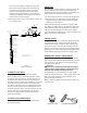
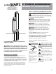
DROP PIPE
Galvanized pipe is recommended for suspending submersible
pumps into the well. Plastic pipe may be used only when
observing the plastic pipe manufacturer’s recommendations of
depth and pressure. Give special consideration to:
1. A safety cable to prevent loss of pump if pipe should break.
2. A torque arrestor just above pump to prevent chafi ng the
cable when pump and pipe twist during the starting and
stopping cycle. (See Figure 1.)
Schedule 40 galvanized pipe is suitable for settings to 600
feet (180m). For deeper settings, use schedule 40 pipe for the
bottom 600 feet (180m), and schedule 80 for the remainder.
Take great care to keep pipes clean and free from pebbles,
scale, and thread chips. Make sound, air-tight connections at all
fi ttings. Pipe sealant is recommended.
CHECK VALVES
Many pumps have a built-in or externally supplied check valve.
For a pump without one, install a check valve immediately
above the pump. Install an additional check valve above the
ground. If the pump is more than 100 feet (30m) below the
wellhead, install another check valve in the drop pipe 100 feet
(30m) above it. For pump settings deeper than 200 feet (60m),
install additional check valves at intervals of 100 feet (30m).
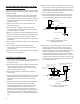
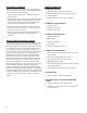
REMOVABLE POPPET CHECK VALVE
4” submersible pumps with a 1-1/4” discharge are supplied
with a spring-loaded, removable poppet check valve assembly.
This check valve can be removed from the pump discharge
when drain back is desired.
WARNING
Fluid draining back through the pump can
cause the pump to rotate backwards. If pump/motor starts
during this time, damage to the pump can occur.
The check valve can be removed using a T-handle poppet
wrench (purchased separately), or with standard needle-nosed
pliers. The poppet assembly is left-hand threaded and is
removed by turning clockwise.
When reinstalling a poppet check valve assembly, tighten it to
15 inch-pounds.
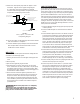
Pressure tank
Pressure switch
Gate valve
Service pipe
Pressure gauge
Pressure relief valve
Spring-loaded
check valve
See Wiring Diagrams
Sanitary well seal
or pitless adapter
Discharge pipe
Submersible cable
Spring-loaded
check valve
(Recommended every 100’/30m)
Safety cable
Drop pipe
Cable
(secured to drop
pipe with tape or
clamps every 10’/3m)
Well casing
Spring-loaded
check valve
at pump discharge
Submersible
pump
Suction screen
Motor
Well screen or
casing perforations
Note: Keep pump at least 5’ from
bottom of well and above well screen
or casing perforations.
Torque arrestor
FIGURE 1
Installation Diagram
Poppet Assembly
T-Handle Poppet Wrench
3