
Product Manual

WELL TEST
Check the pump and well performance before making the fi nal
connection to the discharge system.
1. Install a gate valve on the end of the pipe. Partially open the
valve.
2. Start the pump.
3. Open the valve gradually to give full fl ow.
4. If the discharge is not clear, let the pump run until water
clears. If water does not clear in 30 minutes, stop the pump
and take the necessary steps to correct the condition. After
the water appears clear, check for sand by discharging into a
clean bucket or suitable container.
5. Close valve until maximum required system fl ow rate is
obtained. This should correspond to the cut-in pressure of
the pressure switch. Ensure that the output of the pump
at this setting is not greater than the yield of the well. This
can be checked by monitoring the well drawdown level and
ensuring that the level is stable at the maximum required
system fl ow rate.
Never run the pump unless it is completely
submerged in water. If run without water, the pump and
motor could be damaged. Note also that air drawn into the
pump can cause an airlock under certain conditions.
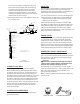
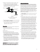
9. A three-wire, three-phase pump does not require a motor
control box . Figure 4 shows a typical wiring diagram
for a three-wire, three-phase installation. A magnetic
contractor with three-leg protection and quick-trip ambient
compensated overload relays must be used.
10. Use an ohm meter to make continuity and insulation checks
after the installation is completed.
11. Place the additional pump nameplate onto the submersible
label and place both onto disconnect switch or circuit
breaker box for future reference.
FIGURE 4
3-wire, 3-phase, 1-1/2 thru 50 HP
Pump Wiring Diagram
Incoming 3-phase power
3-phase submersible motor
Circuit breaker OR
fused disconnect switch
Pressure switch
Magnetic contactor with
3-leg protection and
quick-trip ambient
compensated overload relays
CAUTION
LOW-YIELDING WELL
A low-yielding well exists when the output from the pump is
greater than the yield of the well. It can reduce the water level
to the suction screen so that a mixture of air and water enters
the pump. Pumping may stop since the pump cannot generate
pressure with insuffi cient water. In this case, the column of
water already in the drop pipe holds the check valve closed and
an airlock may develop inside the pump. Because the conditions
ensure neither adequate lubrication of the pump nor proper
cooling for the motor, damage can result if power is not cut off
quickly. Use one or more of the following methods to correct
and/or protect this installation.
1. Install an additional length of drop pipe to place pump lower
in well if possible.
2. Install a Franklin Pumptec or similar electronic drawdown
sensor.
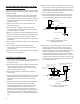
3. Install a fl oatless liquid level control. This device consists of
an electrical relay activated by currents fl owing through the
ground-return circuits of electrodes hung in the well. The
lower (stop) electrode, just above the pump, ensures that
the water level can never be pumped down to the suction
screen. The upper (start) electrode, just below the lowest
static water level, ensures that the pump can start again
as soon as the well has recovered. A fl oatless liquid level
control works in series with the pressure switch. Refer to the
manufacturers instructions provided with the control.
4. Install a fl ow control valve in the discharge line upstream
from the pressure switch. This restricts the output from the
pump without affecting the rate that water can be drawn
from the pressure tank. Nevertheless, a heavy demand
for water could empty the pressure tank, so a tank with a
bonded diaphragm, air cell, or water bag is recommended.
5. Install a smaller pump to avoid over-pumping the well. Have
the dealer size the pump to the well yield.
6. Install a low pressure cut off switch, or a pressure switch
with such an arrangement built in. This protects a shallow-
well pump from losing its prime, but it does not always
provide satisfactory protection to a submersible pump
from the effects of over-pumping the well. This is because
it responds to a loss of pressure at the surface, which may
occur after an air lock has formed inside the pump. Either a
fl oatless liquid level control or a fl ow control valve, in that
order, is recommended in preference to a low-pressure
cutoff switch as protection against over-pumping.
5