
Product Manual


TROUBLESHOOTING
1. PUMP FAILS TO START
a) Electrical trouble - call dealer or electrician
b) Drawdown protection device has pump turned off
c) Overload tripped
d) Reset low pressure cutoff switch (if installed)
2. PUMP FAILS TO DELIVER WATER
a) Air lock in pump
b) Clogged intake screen
c) Insuffi cient well yield
3. PUMP GIVES REDUCED OUTPUT
a) Insuffi cient well yield
b) Worn pump
c) Clogged intake screen
d) Low voltage
e) Incorrect rotation (3-phase only)
4. PUMP CYCLES TOO FREQUENTLY
a) Excessive pressure drop between pressure switch and
pressure tank
b) Cut-in pressure at pressure tank too high
c) Cut-out pressure at pressure tank too low
d) Waterlogged pressure tank
e) Start and stop electrodes of fl oatless liquid level control
set too close together
f) Tank sized too small to meet system requirements
5. OVERLOADS TRIP
a) Electrical trouble - call dealer or electrician
6. PRESSURE SWITCH CYCLES RAPIDLY WHEN PUMP
STARTS
a) Pressure switch too far from pressure tank
b) Improper air charge of tank - adjust to manufacturer’s
recommendations
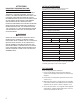
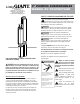
DISCHARGE PLUMBING
Figure 1 illustrates a typical well installation showing above-
ground components. Refer to Figure 1 and the following steps
when installing the discharge plumbing.
1. Install an above-ground check-valve upstream from the
pressure switch.
2. Always install a pressure relief valve in the system. The relief
valve should be capable of discharging the fl ow rate of the
pump at the rated working pressure of the pressure tank.
Locate the relief valve close to the pressure tank.
3. Install a pressure switch between the check valve and the
pressure tank. Refer to Figure 2, 3, or 4 for proper wiring
connections of pressure switch.
4. Install a pressure tank as close as possible to the pressure
switch. Refer to manufacturer’s recommendations for
installation.
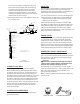
INSTALLATION IN LAKE OR STREAM
A submersible pump is usually isolated at the bottom of a well,
where electrical leakage from its motor and cable presents no
hazard to life. This natural protection is lost when it is installed
it in a lake, pond, stream, or fountain because there is no way
to stop people and animals from entering or touching the
surrounding water. It is recommended that such an installation
be done by a licensed electrician in conformance with all
applicable national and local electrical codes. Grounding as
described in this manual is a minimum requirement, and a
ground fault circuit interrupter (GFCI) is advisable. But in the
absence of explicit national or local regulations, ask the local
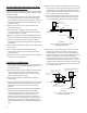
electric utility for guidance. In any case, support the pump
from the shore or bottom at a 15
o
slant to assure proper motor
bearing lubrication. Shield the pump from direct physical
contact by people and animals. Protect and screen the pump
intake to prevent blockage by leaves and weeds, but remember
the need for adequate fl ow over the motor for cooling purposes.
In addition, protect the entire underwater installation from water
currents, ice, boats, anchors, debris, vandalism, and other
hazards.
6