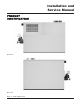
CB-CW(E)-i&s-06 INSTALLATION AND SERVICE MANUAL HYDRONIC HEATING BOILERS and DOMESTIC WATER HEATERS 495,000 - 2,065,000 Btu/hr MODELS WARNING: If the information in this manual is not followed exactly, a fire or explosion may result causing property damage, personal injury or loss of life. – Do not store or use gasoline or other flammable vapors and liquids in the vicinity of this or any other appliance. WHAT TO DO IF YOU SMELL GAS • Do not try to light any appliance.
Hydronic Heating Boilers and Domestic Water Heaters Table of Contents Table of Contents Installation with a Chilled Water System . . . . . . . . . . .26 General Product Information . . . . . . . . . . . . . . . . . . . . . . . . .3 Special Instructions . . . . . . . . . . . . . . . . . . . . . . . . . . . . .3 Unpacking . . . . . . . . . . . . . . . . . . . . . . . . . . . . . . . . . . . .3 Codes . . . . . . . . . . . . . . . . . . . . . . . . . . . . . . . . . . . . . . . .3 Warranty . . . . . . . . .
Installation and Service Manual tube may be caused by too much water velocity through the tubes and is not covered by the appliance manufacturer's warranty (see System Temperature Rise Chart on page 26 for flow requirements). GENERAL PRODUCT INFORMATION Special Instructions SAFETY INFORMATION This manual supplies information for the installation, operation and servicing of the appliance. Read and understand this manual completely before installing unit.
Hydronic Heating Boilers and Domestic Water Heaters 3. Boilers and water heaters are heat producing appliances. To avoid damage or injury, do not store materials against the appliance or the vent-air intake system. Use proper care to avoid unnecessary contact (especially children) with the appliance and vent-air intake components. Follow all clearances from combustibles contained in this manual. 4.
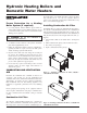
Installation and Service Manual PRODUCT IDENTIFICATION Front View Rear View Figure 1 – Front and Rear View 5
Hydronic Heating Boilers and Domestic Water Heaters INSTALLATION Clearances from Combustible Construction This unit meets the safe lighting performance criteria with the gas manifold and control assembly provided, as specified in the ANSI standards for gas-fired units, ANSI Z21.13/CSA 4.9 and ANSI Z21.10.3/CSA 4.3. Maintain minimum specified clearances for adequate operation. Allow sufficient space for servicing pipe connections, pump and other auxiliary equipment, as well as the unit.
Installation and Service Manual base for combustible floor installation. Install unit over a base of hollow clay tiles or concrete blocks from 8" to 12" thick and extending at least 24" beyond the unit sides. Place tiles or blocks so that the holes line up horizontally to provide a clear passage through the tiles or blocks. Place a 1/2" fireproof millboard over the top of the tile or block base. Place a 20gauge sheet metal cover over the fireproof millboard. Center the unit on the base.
Hydronic Heating Boilers and Domestic Water Heaters Check this filter every month and replace when it becomes dirty. The filter size is 12" x 16" x 1" (30.5cm x 40.6cm x 2.5cm) . You can find this commercially available filter at any home center or HVAC supply store. INSTALLATION Continued Freeze Protection for a Heating Installing Combustion Air Filter Boiler System (if required) 1. Use only properly diluted inhibited glycol antifreeze designed for hydronic systems.
Installation and Service Manual Combustion Air Options CAUTION: Under no circumstances should the mechanical room ever be under a negative pressure. Particular care should be taken where exhaust fans, attic fans, clothes dryers, compressors, air handling units, etc., take away air from the unit. 1. Outside Combustion Air, No Ducts You can direct outside combustion air to this unit using either one or two permanent openings.
Hydronic Heating Boilers and Domestic Water Heaters VENTING INSTALLATION Continued General Information You must supply adequate combustion and ventilation air to this unit. You must provide minimum clearances for the vent terminal from adjacent buildings, windows that open, and building openings. Follow all requirements set forth in the latest edition of the National Fuel Gas Code, ANSI Z223.
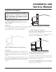
Installation and Service Manual You must locate the air inlet termination elbow at least 12" (30cm) above the roof or above normal snow levels. Keep the vent cap clear of snow, ice, leaves, and debris to avoid blocking the flue. Figure 12 - Vent Termination from Flat Roof 10' or Less from Parapet Wall Figure 10 - Vent Termination from Peaked Roof - 10' or Less From Ridge IMPORTANT: Vent terminations are not shown in Figures 10, 11, 12, and 13.
Hydronic Heating Boilers and Domestic Water Heaters INSTALLATION 2. Outdoor Installation Venting This option uses the installation of special air inlet and vent caps on the unit. See page 13 for venting details. Continued All units are shipped from the factory equipped for conventional negative draft venting. All other optional vent systems require the installation of specific vent kits and venting materials.
Installation and Service Manual Flue Outlet Piping 1. Conventional Negative Draft Venting With this venting option, you must use Type-B double-wall (or equivalent) vent materials. Vent materials must be listed by a nationally-recognized test agency for use as vent materials. Make the connections from the unit vent to the outside stack as direct as possible with no reduction in diameter. Use the National Fuel Gas Code venting tables for double-wall vent to properly size all vent connectors and stacks.
Hydronic Heating Boilers and Domestic Water Heaters INSTALLATION Inspection of a Masonry Chimney A masonry chimney must be carefully inspected to determine its suitability for the venting of flue products. A clay-tile-lined chimney must be structurally sound, straight and free of misaligned tile, gaps between liner sections, missing sections of liner or any signs of condensate drainage at the breeching or clean out.
Installation and Service Manual Flue gas condensate can freeze on exterior walls or on the vent cap. Frozen condensate on the vent cap can result in a blocked flue condition. Some discoloration to exterior building or unit surfaces can be expected. Adjacent brick or masonry surfaces should be protected with a rust resistant sheet metal plate. Outdoor Vent/Air Inlet Location Keep venting areas free of obstructions. Keep area clean and free of combustible and flammable materials.
Hydronic Heating Boilers and Domestic Water Heaters Gas Piping INSTALLATION To safely operate this unit, you must properly size the gas supply piping. See TABLES- F, G, & H for piping and fitting requirements. Gas pipe size may be larger than heater connection. The gas connection for models 495,000 to 745,000 Btu/hr is 1 1/4" NPT and on models 985,000 to 2,065,000 Btu/hr the gas connection to these units is 2" NPT.
Installation and Service Manual The combination gas valves have an integral vent limiting device and does not require venting to atmosphere outside the building. The unit will not operate properly if the reference hose is removed or a vent to atmosphere is installed. COMBINATION VALVE DOWNSTREAM TEST VALVE Optional gas controls may require routing of bleeds and vents to the atmosphere outside the building when required by local codes.
Hydronic Heating Boilers and Domestic Water Heaters not required to have vent or relief lines piped to the outdoors. The termination of the vent limited opening on the combination gas valve/regulator complies with the safety code requirements of CSD-1, CF-190(a) as shipped from the appliance manufacturer without the installation of additional vent lines. INSTALLATION Continued Water heater models do not have downstream test valves, but the rest of the gas train is represented by Figure 19.
Installation and Service Manual 9. If gas pressure is out of range, contact your gas utility, gas supplier, qualified installer or service agency to determine the necessary steps to provide proper gas pressure to the control. 10. If gas supply pressure is within normal range, remove the gas manometer and replace the pressure tap fittings in the gas control as indicated in the following steps. 11. Turn the power switch to the “OFF” position. 4 12. Turn gas valve knob to the “OFF” position. 3 13.
Hydronic Heating Boilers and Domestic Water Heaters 12. If adjustment is necessary, remove the regulator cover screw on the gas valve. Note: If the gas valve under adjustment is located on a manifold assembly monitored by an igniter, the unit may shut down and recycle when the regulator cover screw is removed. This is normal. INSTALLATION Continued 13. Turn the regulator adjustment screw “clockwise” to raise the regulator gas pressure.
Installation and Service Manual Low Water Cutoff (If Equipped) If installing this unit above radiation level, you must install a low water cut-off device at the time of appliance installation. Electronic or float type low water cutoff controls are available as a factory supplied option on all units. Inspect the low water cutoff every six months, including flushing of float types. The low water cutoff control is located on the control panel directly behind the control panel cover.
Hydronic Heating Boilers and Domestic Water Heaters INSTALLATION IMPORTANT: Do not block access to the electrical cover plate when installing electrical conduit. Continued TABLE - J Nominal AMP Draw Data TABLE Btu/Hr Input AMP Draw Data External EMS Connection to Terminal Strip for Stage Firing Control of Burners Approximate Controls Fan Total Amps 495,000 4.6 3.4 8.0 645,000 4.6 3.4 8.0 745,000 4.6 3.4 8.0 985,000 4.6 3.4 8.0 1,255,000 4.6 3.4 8.0 1,435,000 4.6 3.8 8.
Installation and Service Manual BOILER SYSTEM PIPING The drawings in this section show typical boiler piping installations. Before beginning the installation, consult local codes for specific plumbing requirements. Be sure to provide unions and valves at the boiler inlet and outlet so it can be isolated for service. You must install an air separation device in the installation piping to eliminate trapped air in the system. Locate a system air vent at the highest point in the system.
Hydronic Heating Boilers and Domestic Water Heaters Circulator Pump Specifications INSTALLATION 1. Maximum operating pressure for pump must exceed system operating pressure. 2. Maximum water temperature should not exceed nameplate rating. Continued Circulator Pump Requirements This is a low mass, high efficiency hot water boiler which must have adequate flow for quiet, efficient operation. Pump selection is critical to achieve proper operation.
Installation and Service Manual The installer must ensure that the boiler has adequate flow without excessive temperature rise. Low system flow can result in overheating of the boiler water which can cause short burner ON cycles, system noise and in extreme cases, a knocking flash to steam. These conditions indicate the need to increase boiler flow by installation of a larger circulator pump or the installation of a system bypass. System noise may also indicate an oversized boiler.
Hydronic Heating Boilers and Domestic Water Heaters Installation with a Chilled Water System INSTALLATION Continued Pipe refrigeration systems in parallel. Install duct coil downstream at cooling coil.
Installation and Service Manual Boiler Flow Rate CAUTION: The maximum flow rate for models 495,000 - 745,000 Btu/hr is 60 GPM and 90 GPM on 985,000 - 2,065,000 models. Do not exceed the maximum flow rate of the heating boiler. If higher flow rates are required through the boiler, an optional Cupro-Nickel heat exchanger is available. When using a Cupro-Nickel heat exchanger, GPM can be increased by 30 percent. Consult the factory for specific application requirements.
Hydronic Heating Boilers and Domestic Water Heaters INSTALLATION OPERATION Continued FOR YOUR SAFETY READ BEFORE OPERATING 8. Recheck all air vents as described in step 4. 9. Inspect the liquid level in the expansion tank. The system must be full and under normal operating pressure to ensure proper water level in the expansion tank. Ensure that diaphragm type expansion tanks are properly charged and not water logged.
Installation and Service Manual To Turn Off Gas To Appliance 1. Remove the control panel cover to access control panel. 2. Turn power switch to "OFF" position. 3. Turn the manual gas cock clockwise to the "OFF" position. WARNING: Should overheating occur or the gas fail to shut off, turn off the manual gas control valve to the unit. Figure 31 - Control Panel Cover FIG. 32 NO INTERNAL OR EXTERNAL CHANGES WITHOUT WRITTEN APPROVAL BY LOCHINVAR CORPORATION ENGINEERING.
Hydronic Heating Boilers and Domestic Water Heaters OPERATION Continued Figure 35 - Temperature Control Setting Knobs TABLE-L TABLE - M Maximum Set Point Determination Figure 34 - Locating Temperature Control Maximum Setpoint n Temperature Control Settings There are three setting knobs on the temperature control unless your unit is specified as a boiler only with an outdoor air reset option. If your unit is a boiler only with an outdoor air reset option, there are additional controls for this option.
Installation and Service Manual CN8 45 CN1 65 The High-Fire knob specifies the number of degrees below set point that the High-Fire stage shuts down. At that point, the unit will continue to operate at the Low-Fire stage until the set point is reached. 40 70 SHUTDOWN 55 50 60 45 O.A. SENSOR ON ENABLE CN3 OJ1 CN4 SW1 VR3 W1 CN2 60 C10 D4 The temperature control operates a two-stage firing system. The two stages are High-Fire and Low-Fire.
Hydronic Heating Boilers and Domestic Water Heaters OPERATION Boiler Application Continued Standard boiler units are shipped with two sensors; the inlet water temperature sensor and the multi-purpose temperature sensor. The multi-purpose sensor should be used as a system sensor. Boilers with the outdoor air reset option also have an outside air temperature sensor. Temperature Control Sensors This is a two-stage temperature control that controls the burner ignition, pump, and alarm functions.
Installation and Service Manual Remote Mounting of Sensor HOT SURFACE IGNITION SYSTEM You must mount the outside air temperature sensor outside the building. To mount remote sensors, follow the guidelines below. Take care to correctly wire sensors to the unit. Erratic temperature readings can be caused by poor wiring practices. Twist the wires between the unit and the remote sensor. Turn wires at least three or four turns per linear foot of wiring.
Hydronic Heating Boilers and Domestic Water Heaters Ignition and Control Timings OPERATION Proven Pilot Hot Surface Ignition System F9 is standard on models 495,000 through 2,065,000 Btu/hr and M9 is optional on models 495,000 through 2,065,000 Btu/hr with One Hot Surface Ignition Module.
Installation and Service Manual OPERATION AND DIAGNOSTIC LIGHTS TABLE - P Status LED Diagnostic Codes The diagnostic control panel has up to 6 indicating and diagnostic lights to show all major steps of operation and control sensed malfunctions. This panel is located on the left end of the unit. Code Sequence Prepurge TABLE - O Status LED Diagnostic Codes Code Sequence Constant ON Constant OFF System OK, no faults present.
Hydronic Heating Boilers and Domestic Water Heaters 3. Check the pump to be sure it is running properly and that the pump motor is running in the proper direction (see arrow on volute housing). DOMESTIC WATER HEATERS 4. Be sure the installed circulation pipes between the water heater and storage tank are not less than 2 1/2" in diameter on models 985,000 - 2,065,000 Btu/hr. This section applies only to those units used to supply potable hot water for domestic use.
Installation and Service Manual Water Chemistry TABLE - R Pipe Sizing Chart The required temperature rise and the standard pump sizing are based on the heating of potable water with a hardness of 5 to 25 grains per gallon and a total dissolved solids not exceeding 350 ppm. Consult the appliance manufacturer when heating potable water exceeding these specifications.
Hydronic Heating Boilers and Domestic Water Heaters Potable Hot Water Temperature Control Settings DOMESTIC WATER HEATERS Continued Domestic Water Temperatures 6 90° elbows 2 ball valves 2 unions 1 cold water tee WARNING: You must take adequate care to prevent scald injury when storing water at elevated temperatures for domestic use. Not more than 45 feet of straight pipe. This unit has an adjustable temperature control to maintain the desired water temperature set point.
Installation and Service Manual Remember, no water heating system provides exact temperatures at all times. Let the system operate a few days at your desired settings to determine correct settings for your needs. WARNING: Should overheating occur or the gas supply fail to shut off, do not turn off or disconnect the electrical supply to the pump. Instead, shut off the gas supply at a location external to the unit. 1. These units are equipped with an operating temperature control. 2.
Hydronic Heating Boilers and Domestic Water Heaters Lifting Flames: The usual causes for lifting flames are over firing the burner(s), excessive primary air, or high draft. CLEANING AND MAINTENANCE If you observe improper flame patterns, examine the venting system, ensure proper gas supply, and ensure adequate supply of combustion and ventilation air. Listed below are items that must be checked to ensure safe reliable operations. Verify proper operation after servicing.
Installation and Service Manual Heat Exchanger Cleaning Combustion and Ventilation Air 1. While burners are removed, check the heat exchanger surface for sooting. If present, heat exchanger must be cleaned and problem corrected. Proceed as follows. Combustion Air Filter (Models 985,000 2,065,000 Btu/hr Only) This unit has a standard air filter(s) located behind the combustion air inlet panel(s). This filter helps ensure clean air is used for the combustion process.
Hydronic Heating Boilers and Domestic Water Heaters The " (+)" connection on the manometer connects to the tee in the tubing from the units front chamber and the " (-) " connection on the manometer connects to the tee in the small tubing from the burner. CLEANING AND MAINTENANCE CONTINUED Upon a call for heat, the fan will run for about 90 seconds before going into soft lockout. If necessary, turn the power to the unit OFF and then back ON again to recycle the fan.
Installation and Service Manual Adjustment Procedure: 1,435,000, 1,795,000 and 2,065,000 Btu/hr Models 1. Remove the upper front jacket panels from the unit to access the upper chamber. 2. Slightly loosen the screws that attach the fan transition box to the metal base (see Figure 46). 3. Locate the air shutter at the rear of the fan duct (see Figure 47). Move the air shutter towards the rear of the unit to increase air pressure. Move the air shutter towards the front of the unit to decrease air pressure. 4.
Hydronic Heating Boilers and Domestic Water Heaters CLEANING AND MAINTENANCE CONTINUED 7. 8. 9. A faulty hot surface igniter or ignition module must be replaced with an identical part. A specification igniter and ignition module for this specific unit is available from your local distributor. Do not use general purpose field replacement ignition modules or igniters. 10. 11. 12. Ignition System Checkout 1. Turn off gas supply to unit. 2. Turn electric power on. 13. 3.
Installation and Service Manual venters, etc.,). As such, it may be necessary to locate and turn off power to these items before attempting to service the unit. 29. Burners are now firing for approximately 50% of the heater’s input. 30. 24VAC is supplied from the second stage of the electronic temperature control across the 2C and 2NO terminals on the terminal strip on to a control to a relay. 31.
Hydronic Heating Boilers and Domestic Water Heaters Electronic Temperature Controller Relay Board (Controlled by Electronic Temperature Controller and Ignition Module) A small relay board is provided on the 985,000 - 2,065,000 Btu/hr models to switch the blower from low to high speed and to deliver power from the low fire stage (Stage 1) to the high fire stage (Stage 2) depending upon the electronic thermostat's settings.
BK 47 1 120 VAC DOTTED LINE INDICATES OPTIONAL EQUIPMENT CLOSED END SPLICE JUNCTION POINT (ELECTRICALLY SAME) INDICATES "C" NO PR PR LWCO IND. P O G RESET J4 3 2 1 RE S E T 4 1 BL 2 3 BR/W 5 4 6 1 C CN1 2 3 R NO J3 J1 OFF R BR 24V COM R Y BL T LWCO ALARM CONTACTS 24V COM 24V COM TEST SWITCH PROBE T HIGH-FIRE OFFSET OPERATOR DIFFERENTIAL BR Y RATIO DISABLE SHUTDOWN O.A. ENABLE NC OPTIONAL I/O RESET O.A. MAX.
WIRING DIAGRAMS - MAIN UNIT CONNECTIONS MODELS 495,000 - 745,000 BTU/HR TERMINAL STRIP - SENSOR O 5 NO C NC PINS 1 & 2 JUMPERED PROVIDED IF NO OPTIONS ARE ORDERED HI-LIMIT R 2C 1 BK/W AUX HI-LIMIT W OPTIONAL BK W BK/W PR R/O JUMPERED IF NOT PROVIDED O POWER SWITCH BK 13 15 12 11 10 8 7 6 5 4 H PR/W O PT. BOX.
WIRING DIAGRAMS - MAIN UNIT CONNECTIONS MODELS 495,000 - 745,000 BTU/HR (CONTINUED) G CHASSIS GROUND 1 4 11 14 2 12 15 3 10 13 7 10 13 5 8 11 14 6 9 12 15 BK W 1 E 2 BK SPLICE W Y 9 12 15 2 8 11 14 R/O 1 7 10 13 R BLOWER HI-LOW FIRE FULL FIRE SPLICE F Y T O PR GY COM G BURNER GROUND SPLICE 5 PV MV/PV MV LOW AIR INDICATOR PV MV/PV MV GY SPLICE 4 BK Y SPLICE Y 3 120VA C PUMP W BK G VALVE #1 AIR PRESSURE SWITCH HOT SURFACE IGNITER GR BR W GROUND VALVE
G 1 2 ON/OFF POWER SWITCH BK COM FAIL COM OK FAIL HIGH/LOW GAS, AUX. HI-LIMIT AUX. LIMITS, EXT. FLOW SWITCH EXAMPLE DEVICES: BARS REMOVED AND ATTACHED DEVICES IN NON-ALARM STATE. NOTE: SHOWN WITH SHORTING Y Y Y -Y W Y TEST NC 1 BR PR RESET T PR T PROBE SWITCH C P 1 J2 J4 O BL/ BK 3 2 1 6 5 4 J3 T O.A. SENSOR GND RESET 2 3 O NC O.C. 24 VAC LWCO C NO BL/ BK PR AUX.
BL 1 2 3 4 5 6 7 8 9 10 11 12 DISPLAY BOARD I/O RESET O.A. MAX.
Revision 4 (CB-CW(E)-i&s-04) reflects changes made to the O.A. section. Revision 5 (CB-CW(E)-i&s-05) reflects changes made to text on Page 21 and the LBLs on pages 47-51. Revision 6 (ECO #C02870) reflects the addition of a mixing valve to FIG. 41 (page 37) and edits made to the scald warnings.