
Hydronic Heating Boilers and Domestic Water Heaters Installation and Service Manual

INSTALLATION
Continued
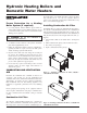
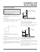
Figure 9 - Combustion Air from Interior Space
All dimensions are based on net free area in square inches.
Metal louvers or screens reduce the free area of a combustion
air opening a minimum of approximately 25%. Check with
louver manufacturers for exact net free area of louvers. Where
two openings are provided, one must be within 12" (30 cm) of
the ceiling and one must be within 12" (30 cm) of the floor of
the mechanical room. Each opening must have a minimum net
free area as specified in TABLE-C, page 12. Single openings
shall be installed within 12" (30 cm) of the ceiling.
The combustion air supply must be completely free of any
flammable vapors that may ignite or chemical fumes which
may be corrosive to the appliance. Common corrosive
chemical fumes which must be avoided are fluorocarbons and
other halogenated compounds, most commonly present as
refrigerants or solvents, such as Freon, trichlorethylene,
perchlorethylene, chlorine, etc. These chemicals, when
burned, form acids which quickly attack the heat exchanger
finned tubes, headers, flue collectors, and the vent system. The
result is improper combustion and a non-warrantable,
premature appliance failure.
Exhaust Fans
Any fan or equipment which exhausts air from the boiler room
may deplete the combustion air supply and/or cause a down
draft in the venting system. Spillage of flue products from the
venting system into an occupied living space can cause a very
hazardous condition that must be corrected immediately. If a
fan is used to supply combustion air to the boiler room, the
installer must make sure that it does not cause drafts which
could lead to nuisance operational problems with the boiler.
VENTING
General Information
You must supply adequate combustion and ventilation air to
this unit. You must provide minimum clearances for the vent
terminal from adjacent buildings, windows that open, and
building openings. Follow all requirements set forth in the
latest edition of the National Fuel Gas Code, ANSI Z223.1, in
Canada, the latest edition of CAN/CGA Standard B149
Installation Code for Gas Burning Appliances and Equipment
or applicable local building codes. Vent installations for
connection to gas vents or chimneys must be in accordance
with Part 7, "Venting of Equipment" of the above-mentioned
standards.
IMPORTANT: Examine the venting system at
least once each year. Check all joints and vent
pipe connections for tightness. Also check for
corrosion or deterioration. If you find any
problems, correct them at once.
Venting Support
Support horizontal portions of the venting system to prevent
sagging. Provide an upward slope of at least 1/4 inch per foot
(21mm/m) on all horizontal runs from the unit to the vertical
flue run or to the vent terminal on sidewall venting
installations.
Do not use an existing chimney as a raceway if another
appliance or fireplace is vented through the chimney. The
weight of the venting system must not rest on the unit. Provide
adequate support of the venting system. Follow all local and
applicable codes. Secure and seal all vent connections. Follow
the installation instructions from the vent material
manufacturer.
Vertical Vent Termination Clearances
and Location
The vent terminal should be vertical and exhaust outside the
building at least 2 feet (0.61m) above the highest point of the
roof within a 10 foot (3.05m) radius of the termination.
The vertical termination must be a minimum of 3 feet (0.91m)
above the point of exit.
A vertical termination less than 10 feet (3.05m) from a parapet
wall must be a minimum of 2 feet (0.61m) higher than the
parapet wall.
Hydronic Heating Boilers and
Domestic Water Heaters
10