
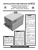
Hydronic Heating Boilers and Domestic Water Heaters Installation and Service Manual

INSTALLATION
Continued
Freeze Protection for a Heating
Boiler System (if required)
1. Use only properly diluted inhibited glycol antifreeze
designed for hydronic systems. Inhibited propylene glycol
is recommended for systems where incidental contact with
drinking water is possible.
WARNING: Do not use undiluted or
automotive type antifreeze.
2. A solution of 50% antifreeze will provide maximum
protection of approximately -30°F.
3. Follow the instructions from the antifreeze manufacturer.
Quantity of antifreeze required is based on total system
volume including expansion tank volume.
4. Glycol is denser than water and changes the viscosity of
the system. The addition of glycol will decrease heat
transfer and increase frictional loss in the boiler and related
piping. A larger pump with more capacity (15% to 25%
more) may be required to maintain desired flow rates and
prevent a noise problem in a glycol system.
5. Local codes may require a back flow preventer or actual
disconnect from city water supply when antifreeze is
added to the system.
COMBUSTION AND VENTILATION
AIR
Provisions for combustion and ventilation air must be in
accordance with Section 5.3, Air for Combustion and
Ventilation, of the latest edition of the National Fuel Gas Code,
ANSI Z223.1, in Canada, the latest edition of CAN/CGA-
B149 Installation Code for Gas Burning Appliances and
Equipment, or applicable provisions of the local building
codes.
Provide properly-sized openings to the equipment room to
assure adequate combustion air and proper ventilation when
the unit is installed with conventional venting or sidewall
venting.
Combustion Air Filter
The 985,000 - 2,065,00 Btu/hr models have a standard air
filter(s) located behind the combustion air inlet panel(s). This
filter helps ensure clean air is used for the combustion process.
Check this filter every month and replace when it becomes
dirty. The filter size is 12" x 16" x 1" (30.5cm x 40.6cm x
2.5cm) . You can find this commercially available filter at any
home center or HVAC supply store.
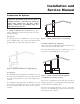
Installing Combustion Air Filter
To install the filter(s), remove the combustion air inlet panel(s).
The 985,000 - 1,435,000 Btu/hr models have one combustion air
inlet panel located on the left front of the unit (see Figure 4). The
1,795,000 and 2,065,000 Btu/hr models have two combustion air
inlet panels located on the left and right front of the unit (see
Figure 5).
1. Loosen knurled knob at the bottom of the control panel
cover.
2. Pull the bottom of the panel(s) out and down to remove.
3. Place filter(s) in opening(s).
4. Replace combustion air inlet panel(s).
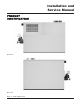
Figure 4 - Installing Combustion Air Filter, 985,000 -
1,435,000 Btu/hr Models
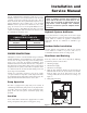
Figure 5 - Installing Combustion Air Filters, 1,795,000 and
2,065,000 Btu/hr Models
Hydronic Heating Boilers and
Domestic Water Heaters
8