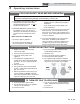
KBXII-USER Rev B User’s Information Manual Models: 400 - 801 WARNING If the information in this manual is not followed exactly, a fire or explosion may result causing property damage, personal injury or loss of life. This appliance MUST NOT be installed in any location where gasoline or flammable vapors are likely to be present. WHAT TO DO IF YOU SMELL GAS • Do not try to light any appliance. • Do not touch any electric switch; do not use any phone in your building.
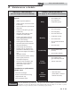
Contents HAZARD DEFINITIONS ..................................................... 2 PLEASE READ BEFORE PROCEEDING ......................... 3 1. PREVENT COMBUSTION AIR CONTAMINATION ..... 4 2. MAINTENANCE SCHEDULE ....................................... 5 Maintenance Procedures ................................................... 6 Boiler Must Be Serviced and Maintained .................... 6 Check Boiler Area ......................................................... 6 Check Pressure Temperature Gauge.......
User’s Information Manual Please read before proceeding NOTICE NOTICE The Knight XL Installation and Operation Manual along with the Knight XL Service Manual are for use only by a qualified heating installer/service technician. Refer only to this User’s Information Manual for your reference. Improper installation, adjustment, alteration, service or maintenance can cause property damage, personal injury (exposure to hazardous materials) or loss of life.
User’s Information Manual 1 Prevent combustion air contamination WARNING WARNING If the boiler combustion air inlet is located in any area likely to cause contamination, or if products which would contaminate the air cannot be removed, you must have the combustion air and vent re-piped and terminated to another location. Contaminated combustion air will damage the boiler, resulting in possible severe personal injury, death, or substantial property damage.
User’s Information Manual 2 Maintenance schedule Service technician (see the Knight XL Service Manual) Owner maintenance (see pages 6 - 8 for detailed instructions) ANNUAL START-UP General: • Address reported problems • Inspect interior; clean and vacuum if necessary • Clean condensate trap and fill with fresh water • Check for leaks (water, gas, flue, condensate) • Verify flue and air lines in good condition and sealed tight • Check system water pressure/ system piping/expansion tank • Ch
User’s Information Manual 2 Maintenance schedule Maintenance procedures Read the list of potential materials listed in Table 1A on page 4 of this manual. If any of these products are in the room from which the boiler takes its combustion air, they must be removed immediately or the boiler combustion air (and vent termination) must be relocated to another area.
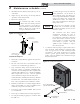
User’s Information Manual 2 Maintenance schedule 3. Fill with fresh water until the water begins to pour out of the drain. 4. Replace the cap. Press the cap onto the trap until the cap makes contact with the drain. (continued) NOTICE 5. Replace the retaining screw. The condensate trap (FIG. 2-1) must WARNING be filled with water during all times of boiler operation to avoid flue gas emission from the condensate drain line. Failure to fill the trap could result in severe personal injury or death.
User’s Information Manual 2 Maintenance schedule Check air vents Have leaks fixed at once by a qualified service technician. Failure to comply could result in severe personal injury, death, or substantial property damage. Replace the front access door. WARNING 1. Reference FIG. 2-3 below. 2. Visually inspect vent to make sure that no leaks are present. 3. If there is leaking, tighten the pin valve. 3. 4. If the leaking continues, replace the air vent.
User’s Information Manual 3 Operating instructions FOR YOUR SAFETY READ BEFORE OPERATING WARNING: If you do not follow these instructions exactly, a fire or explosion may result causing property damage, personal injury, or loss of life. A. This appliance does not have a pilot. It is equipped with an ignition device which automatically lights the burner. Do not try to light the burner by hand. B. BEFORE OPERATING smell all around the appliance area for gas.
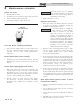
User’s Information Manual 4 SMART SYSTEM control module Knight XL control module Use the control panel (FIG. 4-1) to set temperatures, operating conditions, and monitor boiler operation.
User’s Information Manual 4 SMART SYSTEM control module Night Setback Override Any Night Setback On trigger currently active or scheduled within the next seven (7) days can be skipped. To skip a trigger, press the MENU key for 5 seconds. Once password “0000” appears, press the SAVE key. Rotate the NAVIGATION dial to NSB OVERRIDE, and press the NAVIGATION dial. A list of the current (if active) and upcoming NSB On triggers will appear.
User’s Information Manual 4 SMART SYSTEM control module Figure 4-2 Status Display Screen B A (CALL FOR HEAT) (BOILER STATUS) C (OPERATIONAL INFORMATION) F D (RIGHT SELECT KEY) (LEFT SELECT KEY) E (NAVIGATION DIAL) Status Display Screens Section A (Boiler Status Bar) Display Description STANDBY The unit has not received a call for heat from a remote thermostat nor has it received a call for heat from a DHW thermostat.
User’s Information Manual 4 SMART SYSTEM control module Section Status Display Screens (cont’d) Display Description SYSTEM: TANK: OUTDOOR: The temperature read by the tank sensor (if connected). The temperature read by the outdoor sensor (if connected). The temperature read at the inlet to the heat exchanger. OUTLET TEMP: The temperature read at the outlet of the heat exchanger. FLUE TEMP: FLAME CURRENT: The temperature difference between the inlet and the outlet of the heat exchanger.
User’s Information Manual 4 SMART SYSTEM control module Section Status Display Screens (cont’d) Display Description Turning the NAVIGATION dial will select the next or previous Status Screen. Pressing the NAVIGATION dial will show the next fault, NSB (Night Setback) trigger, or ramp delay setting. Pressing the NAVIGATION dial will select the setting indicated by the cursor. E (NAVIGATION Dial Function) Pressing the NAVIGATION dial will display the Set Points Screen.
User’s Information Manual Notes 15
Revision Notes: Revision A (ECO C05747) initial release. Reflects the new model numbers for the Knight XL upgrade. Revision B (ECO C07072) reflects the change in design of the manual air vent valve, update of FIG. 2-3 on page 8 and the clarification of the user password information on pages 10 and 11.