C(F,H,P)X-SER Rev B Copper-fin II/IIE Boiler, Water Heater and Pool Heater Service Manual Models: 402 - 2072 (Boiler & Water Heater) Models: 502 - 2072 (Pool Heater) WARNING This manual must only be used by a qualified heating installer / service technician. Read all instructions, including this manual and the Installation and Operation Manual, before installing. Perform steps in the order given. Failure to comply could result in severe personal injury, death, or substantial property damage.
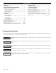
Contents CONTENTS........................................................................ 2 Hazard Definitions .............................................................. 2 PLEASE READ BEFORE PROCEEDING ........................ 3 Handling Ceramic Fiber Materials ...................................... 3 When servicing appliance ............................................. 3 Appliance operation ..................................................... 3 Appliance water ........................................
Copper-fin II/IIE Boiler, Water Heater and Pool Service Manual Please read before proceeding WARNING Installer – Read all instructions, including this manual and the Installation and Operation Manual, before installing. Perform steps in the order given. User – This manual is for use only by a qualified heating installer/service technician. Refer to the User’s Information Manual for your reference.
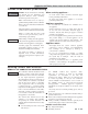
Copper-fin II/IIE Boiler, Water Heater and Pool Service Manual What is in this manual? Service Maintenance The Copper-fin display • Service and maintenance schedules • Address reported problems • Inspect appliance area and appliance interior • Check all piping for leaks • Flue vent system and air piping • Combustion air filter • Check water system • Check expansion tank • Check relief valve • Check igniter • Check all appliance wiring • Flame inspection • Check flue gas passageways • Inspect and clean b
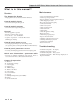
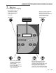
Copper-fin II/IIE Boiler, Water Heater and Pool Service Manual 1 Service The Copper-fin display • Hold 5 seconds to enter code Input Mode (Menu Mode) • Press to move up one level in Menu Mode or to exit Menu Mode DISPLAY SCREEN MENU/EXIT UP • Press to turn heater off or back on • Press to select a menu item • Press after parameter programming to store parameter data • Press to exit Service Mode DOW N • Press to change boiler water temperature and/or tank water temperature set point during normal op
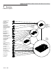
Copper-fin II/IIE Boiler, Water Heater and Pool Service Manual 1 Service Control inputs OUTDOOR SENSOR (OPTIONAL) SYSTEM SUPPLY/ ENABLE SENSOR (OPTIONAL) SYSTEM RETURN/ POOL SENSOR (OPTIONAL ON BOILER) (STD ON POOL HEATER) LOW VOLTAGE CONNECTION BOARD SYSTEM PUMP SPEED (OPTIONAL) SENSOR CONNECTION BOARD (BOILER AND POOL HEATER ONLY) CASCADE DHW THERMOSTAT (OPTIONAL) ROOM THERMOSTAT/ ZONE CONTROL (OPTIONAL) SEQUENCER BUILDING MANAGEMENT SYSTEM (FIELD PROVIDED) LOUVER PROVING SWITCH (FIELD PROVIDED) T
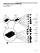
Copper-fin II/IIE Boiler, Water Heater and Pool Service Manual 1 Service (continued) Control outputs MODBUS BOARD (OPTIONAL) MODBUS LOW VOLTAGE CONNECTION BOARD 0-10V POWER CASCADE THREE WAY VALVE (OPTIONAL ON BOILER) (STD ON POOL HEATER) LOUVER RELAY BUILDING MANAGEMENT SYSTEM RUN TIME CONTACTS ALARM CONTACTS SMART SYSTEM CONTROL BOARD ALARM (OPTIONAL) HEATER PUMP (BOILER ONLY) SYSTEM PUMP RELAY DHW PUMP RELAY (BOILER) DHW PUMP (WATER HEATER) HOT SURFACE IGNITER BLOWER GAS VALVES DISPLAY PANEL PC
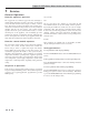
Copper-fin II/IIE Boiler, Water Heater and Pool Service Manual 1 Service General Operation How the appliance operates Access modes The Copper-fin uses a finned copper tube heat exchanger to transfer heat from the flue products to the water. An electronic control module monitors various inputs to initiate a call for heat. The blower provides both primary and secondary air to the burner and forces the flue products out of the combustion chamber and into the vent system.
Copper-fin II/IIE Boiler, Water Heater and Pool Service Manual 1 Service (continued) Sequence of operation Table 1A_Sequence of Operation - Space Heating and DHW OPERATION DISPLAY 1. The manual reset high limit (optional) must be closed before any action will take place. HTR: Standby OUT: 123.8F(129) 2. Upon a call for heat the control turns on the appropriate pumps (system and boiler pumps for space heating; DHW pump for DHW call). The flow switch and low water cutoff (if equipped) must close.
Copper-fin II/IIE Boiler, Water Heater and Pool Service Manual 1 Service Sequence of operation Table 1A_(continued from previous page) Sequence of Operation - Space Heating and DHW OPERATION DISPLAY 9. If the DHW thermostat remains on for more than 30 minutes, and the space heating call for heat is also on, then the control will turn on the boiler pump, turn off the DHW pump after 2 seconds, and resume firing based on the space heating set point.
Copper-fin II/IIE Boiler, Water Heater and Pool Service Manual 1 Service (continued) Display panel menu access Table 1B_Use this procedure to access menus from the display panel Note: Not all menu listings shown above are available on water heaters.
Copper-fin II/IIE Boiler, Water Heater and Pool Service Manual 1 Service Display panel parameter access Table 1C_This is a typical example of accessing a parameter, shown for parameter K2, SH pump delay Cascade BMS 12
Copper-fin II/IIE Boiler, Water Heater and Pool Service Manual 1 Service (continued) Parameter table Table 1D_This table lists SMART SYSTEM control module parameters and where to access them GENERAL TEMPERATURE SETTINGS B C OUTDOOR RESET DHW SETTINGS FUNCTIONS A DATA LOGGING Menu D E F Sub Item Description User Access See Page Display Modify Installer Access Display Modify 1 2 3 4 5 6 7 8 1 2 3 4 5 6 7 1 2 3 4 User Code Time and Date Software Version Temperature Units SH Night Setbac
Copper-fin II/IIE Boiler, Water Heater and Pool Service Manual 1 Service Parameter table (continued) Table 1D_(continued from previous page) This table lists SMART SYSTEM control module parameters and where to access them SERVICE NOTIFICATION PUMPS BMS CASCADE CONTROL MODES ANTICYCLING Menu 14 G H I J K L Sub Item Description User Access See Page Display Modify Installer Access Display Modify 1 2 3 4 1 2 Anti-cycle Delay Anti-cycle Override Differential Min On/Off Time Stages 1, 3
Copper-fin II/IIE Boiler, Water Heater and Pool Service Manual 1 Service (continued) Viewable and changeable control parameters CAUTION Before changing parameters, note the settings so that the unit can be returned to its original operating parameters. A: General A1: User code The User Code allows the user to access and change a limited number of control parameters. The access code can be changed by the user or the installer to a code of their choosing.
Copper-fin II/IIE Boiler, Water Heater and Pool Service Manual 1 Service B3: SH Maximum set point The SH maximum set point sets the maximum water temperature set point that can be used for space heating. The user or installer will not be able to program the control with a higher SH set point. This parameter can only be changed by the installer by accessing parameter B3. The temperature range of this parameter is 32°F (0°C) to 230°F (110°C) (space heating) or 32°F (0°C) to 105°F (40°C) (pool heater).
Copper-fin II/IIE Boiler, Water Heater and Pool Service Manual 1 Service (continued) D5: Freeze protection pump on E4: DHW/SH switching time (boiler only) In order to prevent the water in the heater from freezing, the SMART SYSTEM control turns on the boiler pump whenever the inlet temperature goes below the minimum temperature. This temperature can be adjusted by using parameter D5. The range of this parameter is 32°F (0°C) to 104°F (40°C). The default value is 45°F (7°C).
Copper-fin II/IIE Boiler, Water Heater and Pool Service Manual 1 Service Figure 1-1_Outdoor Air Reset Curve F: Outdoor air reset (boiler only) F3: Maximum SH set point Outdoor air reset operation When the outdoor air sensor is installed, the control will calculate the water temperature set point based on the outdoor air temperature. As the outdoor air temperature drops, the water temperature set point increases. This feature allows the unit to be more efficient in periods of mild weather, see FIG.
Copper-fin II/IIE Boiler, Water Heater and Pool Service Manual 1 Service (continued) F6: Outdoor air shutdown differential G2: Anti-cycle override differential The outdoor air shutdown differential parameter is the number of degrees below parameter F5 the outdoor air temperature must go before the unit will respond to a SH demand. This parameter can be changed by the user or the installer by accessing parameter F6. The temperature range of this parameter is 0°F (0°C) to 90°F (50°C).
Copper-fin II/IIE Boiler, Water Heater and Pool Service Manual 1 Service Figure 1-2_Ramp Delay Interval H: Control modes H3: BMS input (active / inactive) H1: SH controlling sensor (boiler only) When the building management input is enabled, the control modulates the unit or the cascade based on the voltage on the 0-10V input on the connection board. The 0-10V input may control either the modulation of the unit(s), or the set point.
1 Copper-fin II/IIE Boiler, Water Heater and Pool Service Manual Service (continued) I: Cascade J: Building Management System (BMS) I1: Cascade address J1: BMS type The boiler designated as the Leader needs to be programmed with address 0. All the Member boilers require addresses from 1 to 7, and the addresses must be different for each Member. The addresses can be in any order, regardless of the order in which the units are wired together.
Copper-fin II/IIE Boiler, Water Heater and Pool Service Manual 1 Service J7: Set point at high voltage K4: System pump mode (boiler only) This setting determines the set point used by the unit or cascade when the BMS voltage is at or above the Voltage at Maximum setting. This parameter is only active when the BMS type is set to Set Point. This parameter can be adjusted by the installer by accessing parameter J7.
Copper-fin II/IIE Boiler, Water Heater and Pool Service Manual 2 Maintenance Maintenance and annual startup Table 2A_Service and Maintenance Schedules Service technician (see the following pages for instructions) Owner maintenance (see the User’s Information Manual for instructions) • Check appliance area General: • Address reported problems • Inspect interior; clean and vacuum if necessary; • Check for leaks condensate) (water, gas, Daily • Check pressure/temperature gauge flue, ANNUAL START-UP
Copper-fin II/IIE Boiler, Water Heater and Pool Service Manual 2 Maintenance WARNING Follow the service and maintenance procedures given throughout this manual and in component literature shipped with the appliance. Failure to perform the service and maintenance could result in damage to the appliance or system. Failure to follow the directions in this manual and component literature could result in severe personal injury, death, or substantial property damage.
Copper-fin II/IIE Boiler, Water Heater and Pool Service Manual 2 Maintenance (continued) Check relief valve Inspect/replace hot surface igniter 1. Inspect the relief valve and lift the lever to verify flow. Before operating any relief valve, ensure that it is piped with its discharge in a safe area to avoid severe scald potential. Read the Water Connections Section of the Installation and Operation Manual before proceeding further.
Copper-fin II/IIE Boiler, Water Heater and Pool Service Manual 2 Maintenance Check all wiring 1. Inspect all wiring, making sure wires are in good condition and securely attached. Check control settings 1. Set the SMART SYSTEM control module display to Parameter Mode and check all settings. See Section 1 of this manual. Adjust settings if necessary. See Section 1 of this manual for adjustment procedures. 2. Check settings of external limit controls (if any) and adjust if necessary.
Copper-fin II/IIE Boiler, Water Heater and Pool Service Manual 2 Maintenance (continued) Access to the burner will require the following steps: Checking combustion air pressure 1. Turn off main electrical power to the appliance. 2. Turn off main manual gas shutoff to the appliance. 3. Remove the lower outer front access door. The combustion air fans are factory pre-set and should not require adjustment in most cases.
Copper-fin II/IIE Boiler, Water Heater and Pool Service Manual 2 Maintenance Adjusting combustion air pressure The following is a recommended method for setting the combustion air pressure. The following pressure settings are for installations up to 4000 feet altitude. Contact the factory for high altitude air pressure settings. Upon removal of the upper front doors, locate the capped tee in the pressure tubing that connects between the inner top and the gas valves.
Copper-fin II/IIE Boiler, Water Heater and Pool Service Manual 2 Maintenance (continued) Figure 2-4_Measuring manifold gas pressure MANIFOLD PRESSURE PRESSURE REGULATOR ADJUSTMENT (UNDER CAP SCREW) INLET CHAMBER PRESSURE TEE OUTLET GAS VALVE CONTROL KNOB MANOMETER TO BARBED FITTING TABLE 2B Net Manifold Pressure Regulator Pressure Less Front Chamber Pressure MODEL 402 - 752 992 - 2072 Nat. Gas 1.8'' w.c. 1.2'' w.c. LP 4.6’’ w.c. 4.6’’ w.c.
Copper-fin II/IIE Boiler, Water Heater and Pool Service Manual 2 Maintenance Inspect and clean the heat exchanger 1. Turn off the main electrical power to the appliance. 2. Turn off the main manual gas shutoff to the appliance. 3. Remove the lower outer fron access door. 4. Disconnect the manifold(s) from the gas train using the union(s) just below each gas valve. 5. Disconnect wiring to the hot surface igniter(s) and ground. 6. Disconnect burner pressure line at burner. 7.
Copper-fin II/IIE Boiler, Water Heater and Pool Service Manual 3 Troubleshooting WARNING Label all wires prior to disconnection when servicing controls. Wiring errors can cause improper and dangerous operation. Always disconnect power to the appliance before servicing. Failure to comply could result in severe personal injury, death, or substantial property damage. Never jumper (bypass) any device except WARNING for momentary testing as outlined in the Troubleshooting chart.
Copper-fin II/IIE Boiler, Water Heater and Pool Service Manual 3 Troubleshooting Table 3A Troubleshooting Chart - No Display FAULT CAUSE CORRECTIVE ACTION • Check external line switch, fuse, or breaker. - No 120 VAC supplied to unit. • Check position of ON/OFF switch. Turn switch to the ON position. • Check 120 VAC through the ON/OFF switch. voltage through switch, replace switch. No Display No - Bad wiring connection.
Copper-fin II/IIE Boiler, Water Heater and Pool Service Manual 3 Troubleshooting (continued) Checking temperature sensors The appliance temperature sensors (inlet water, outlet water, system water, tank water, flue, and outdoor air) are all resistance type devices. The following tables show the correct values for the sensors at various temperatures. Use an ohmmeter to read the resistance of the sensor at a known temperature.
Copper-fin II/IIE Boiler, Water Heater and Pool Service Manual 3 Troubleshooting Table 3D Troubleshooting Chart - Noisy System FAULT CAUSE CORRECTIVE ACTION - Gas supply problem. • Refer to the Gas Connections Section of the Installation and Operation Manual for detailed information concerning the gas supply. - Gas/air mixture problem. • Refer to the Checking Manifold Gas Pressure and Combustion Analysis Procedure on pages 27 and 28 of this manual for the proper settings.
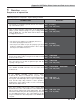
Copper-fin II/IIE Boiler, Water Heater and Pool Service Manual 3 Troubleshooting (continued) Table 3E Troubleshooting Chart - Fault Messages Displayed on Operator Interface FAULT DESCRIPTION - Either the optional manual reset low gas pressure switch or the optional manual reset high gas pressure switch tripped. Gas Pressure SW (Will require a manual reset once the condition has been corrected.) - Models 992 - 2072 (natural gas) - Automatic Reset Low Gas is open.
Copper-fin II/IIE Boiler, Water Heater and Pool Service Manual 3 Troubleshooting Table 3E (continued from previous page) Troubleshooting Chart - Fault Messages Displayed on Operator Interface FAULT DESCRIPTION CORRECTIVE ACTION The unit has failed to prove burner flame upon ignition. • Inspect igniter and associated wiring for damage and connection. Reference page 25 of this manual for removal and cleaning procedure. Replace if necessary. • Check for proper electrical grounding of unit.
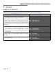
Copper-fin II/IIE Boiler, Water Heater and Pool Service Manual 3 Troubleshooting (continued) Table 3E (continued from previous page) Troubleshooting Chart - Fault Messages Displayed on Operator Interface FAULT DESCRIPTION CORRECTIVE ACTION The unit was running and lost the flame signal. • Inspect igniter and associated wiring for damage and connection. Reference page 25 of this manual for removal and cleaning procedure. Replace if necessary. • Check for proper electrical grounding of unit.
Copper-fin II/IIE Boiler, Water Heater and Pool Service Manual 3 Troubleshooting Table 3E (continued from previous page) Troubleshooting Chart - Fault Messages Displayed on Operator Interface FAULT DESCRIPTION CORRECTIVE ACTION The outlet water temperature has exceeded • Verify setting of adjustable high limit. the setting of the adjustable high limit. • Verify that the system is full of water and that all air has been properly purged from the system.
Copper-fin II/IIE Boiler, Water Heater and Pool Service Manual 3 Troubleshooting (continued) Table 3E (continued from previous page) Troubleshooting Chart - Fault Messages Displayed on Operator Interface FAULT DESCRIPTION CORRECTIVE ACTION Louver Proving (Lockout will reset automatically after 5 minutes or may be reset immediately once An optional remote proving switch is not making. condition has been corrected. Press the RESET button on the SMART SYSTEM display to reset.
Copper-fin II/IIE Boiler, Water Heater and Pool Service Manual 3 Troubleshooting Table 3E (continued from previous page) Troubleshooting Chart - Fault Messages Displayed on Operator Interface FAULT DESCRIPTION CORRECTIVE ACTION The temperature rise across the heat • Verify that the system is full of water and that all air exchanger has exceeded the set parameters has been properly purged from the system. for the appliance. • Verify that the appliance is piped properly into the heating system.
Copper-fin II/IIE Boiler, Water Heater and Pool Service Manual 3 Troubleshooting (continued) Table 3E (continued from previous page) Troubleshooting Chart - Fault Messages Displayed on Operator Interface FAULT Parameters Progr DESCRIPTION CORRECTIVE ACTION After downloading parameters from a laptop, • Press the ENTER/RESET button on the Smart the main control board must be reset. System display panel. (Will require a manual reset once the condition has been corrected.
Copper-fin II/IIE Boiler, Water Heater and Pool Service Manual 3 Troubleshooting Table 3E (continued from previous page) Troubleshooting Chart - Fault Messages Displayed on Operator Interface FAULT DESCRIPTION CORRECTIVE ACTION The main control board has detected an • Cycle main power. Watch Dog Error internal fault. • Replace the main control board. Write EEProm The main control board has detected an • Cycle main power. internal fault. • Replace the main control board.
NOTES 43
Revision Notes: Revision A (ECO #C08226) initial release. Revision B (ECO #C08896) reflects the update of Parameter Table 1-D on pages 13 - 14 and Parameter information on pages 17 and 19. Table 3B on page 33 for sensor information was also updated.