Service Manual Models: ER152, ER202, ER252, ER302, and ER402 WARNING This manual must only be used by a qualified heating installer / service technician. Read all instructions, including this manual and the EnergyRite Installation and Operation Manual, before installing. Perform steps in the order given. Failure to comply could result in severe personal injury, death, or substantial property damage. Save this manual for future reference.
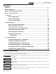
Service Manual Contents Contents . . . . . . . . . . . . . . . . . . . . . . . . . . . . . . . . . . . . . . . . . . . . . . . . . . . . . . . 2 Hazard definitions . . . . . . . . . . . . . . . . . . . . . . . . . . . . . . . . . . . . . . . . . . . . . . . . 2 Please read before proceeding . . . . . . . . . . . . . . . . . . . . . . . . . . . . . . . . . . . . . 3 What is in this manual? . . . . . . . . . . . . . . . . . . . . . . . . . . . . . . . . . . . . . . . . . . . 5 1. Service . . . . . . . . . .
Service Manual Please read before proceeding WARNING Installer – Read all instructions, including this manual and the EnergyRite Installation and Operation Manual, before installing. Perform steps in the order given. NOTICE User – This manual is for use only by a qualified heating installer/service technician. Refer to the EnergyRite User’s Information Manual for your reference. Have this pool heater serviced/inspected by a qualified service technician at least annually.
Service Manual Please read before proceeding When servicing pool heater – • To avoid electric shock, disconnect electrical supply before performing maintenance. • To avoid severe burns, allow the pool heater to cool before performing maintenance. Pool heater operation – • Do not block flow of combustion or ventilation air to the pool heater. • Should overheating occur or gas supply fail to shut off, do not turn off or disconnect electrical supply to circulator.
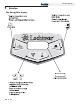
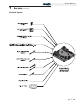
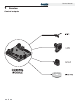
Service Manual What is in this manual? Service The EnergyRite display • Display panel readout, buttons and their functions Maintenance • Service and maintenance schedules • Inspect pool heater area and pool heater interior • Check all piping for leaks Control module inputs • Check air openings • Control module inputs and options • Flue vent system and air piping • Check water system Control module outputs • Check pool heater relief valve (if applicable) • Control module outputs and options • Inspe
Service Manual 1 Service The EnergyRite display 6
Service Manual 1 Service (continued) Control inputs 7
Service Manual 1 Service Control outputs 8
Service Manual 1 Service (continued) General Operation How the pool heater operates The EnergyRite uses a copper finned tube heat exchanger and an electronic control module. The blower provides both primary and secondary air to the burners and forces the flue products out of the combustion chamber and into the vent system. The combination gas valve both regulates the manifold pressure and provides gas to the manifold, which then supplies the burners.
Service Manual 1 Service Access setup menu Table 1A Use this procedure to access the Setup Menu from the display panel The pool heater will continue to operate while the Setup Menu is being accessed. To adjust settings, press the MENU button until the desired screen is displayed. Use the UP and DOWN buttons to adjust the setting within the screen. By pressing the MENU or POOL/SPA button the new setting will be stored into memory and the next screen will be displayed.
Service Manual 1 Service (continued) Access service menu Table 1B Use this procedure to access the Service Menu from the display panel Service menu descriptions Outlet temperature The screens may also be scrolled backwards by pressing the UP button. The pool heater will continue to operate while the Service Menu is being accessed. To exit the Service Menu press the POOL/SPA button. The control will exit the Service Menu automatically after 20 minutes of inactivity.
Service Manual 1 Service Keypad lockout Locking the keypad Unlocking the keypad The user has the ability to lock the keypad to prevent unauthorized adjustments. To lock the keypad, the user must first select and input a passcode. See Set Passcode under Setup Menu Descriptions on page 10 of this manual. Once a passcode has been set, press and hold the UP and DOWN buttons simultaneously for 5 seconds. The Display Screen will show ENTER PASSCODE. The digit on the far left will be blinking.
Service Manual 2 Maintenance Maintenance and annual startup Table 2A Service and Maintenance Schedules Service technician (see the following pages for instructions) Owner maintenance (see the EnergyRite User’s Information Manual for instructions) General: • Address reported problems • Inspect interior; clean and vacuum if necessary • Check for leaks (water, gas, and flue) Daily • Check pool heater area • Verify flue and air lines in good condition and sealed tight ANNUAL START-UP • Check control
Service Manual 2 Maintenance WARNING Follow the service and maintenance procedures given throughout this manual and in component literature shipped with the pool heater. Failure to perform the service and maintenance could result in damage to the pool heater or system. Failure to follow the directions in this manual and component literature could result in severe personal injury, death, or substantial property damage.
Service Manual 2 Maintenance (continued) Inspect ignition and flame sense electrodes 1. Remove the ignition and flame sense electrodes from the combustion chamber door. 2. Remove any deposits accumulated on the ignition/flame sense electrode using sandpaper. If the electrodes cannot be cleaned satisfactorily, replace with new ones. 3. Replace ignition/flame sense electrode, making sure gasket is in good condition and correctly positioned. Check ignition ground wiring 1.
Service Manual 2 1. Maintenance Burner removal and cleaning procedure: WARNING a) Turn off main power to the pool heater. b) Turn off main manual gas shutoff to the pool heater. c) Remove the front and top outer jacket panels. d) Disconnect the gas supply from the gas valve manifold assembly with a field supplied union before the gas valve. Disconnect the union between the gas valve and the manifold. The combustion chamber lining in this appliance contains ceramic fiber materials.
Service Manual 2 Maintenance (continued) Heat exchanger cleaning 2. Combustion Air Fan: The combustion air fan should be checked every 6 months or each season of operation. Clean fan as required when installed in a dust or dirt contaminated location. 3. Water Circulating Pump: Ensure that the filter system pump is providing adequate flow to the pool heater. Backwash and clean filter as required to maintain proper flow. 4.
Service Manual 2 Maintenance Combustion Air Shutter Adjustment TABLE - 2B AIR SHUTTER ADJUSTMENT OPENING This pool heater uses a fan assisted combustion process. The fan air shutter is factory preset and should not need adjusting in most cases. If adjustment is required, the fan air shutter may be manually adjusted to a dimension specified for each model (see Table 2B).
Service Manual 2 Maintenance (continued) Differential air pressure measurement Gas train and controls The differential air pressure measurement can be checked with a slack tube manometer (FIG. 2-8). Disconnect the two tubes from the air pressure switch and connect one to each side of a manometer. Turn on the pool heater and allow the combustion air fan to operate.
Service Manual 2 Maintenance Facts about water chemistry Factors which affect pool and spa water and, more importantly, the efficiency of your new pool/spa heater are: We recommend using a four-way test kit to monitor the following levels (see Table 2D) to ensure proper operation of your pool heater: 1. Proper Filtration 2. Proper Circulation TABLE - 2D RECOMMENDED POOL CHEMISTRY LEVELS Test Recommended Level 3. Disinfection and Oxidation Correct pH 7.2 - 7.8 4.
Service Manual 2 Maintenance (continued) Heat exchanger inspection 3. Tubes This pool heater is especially designed to operate without accumulation of scale in the heat exchanger, even in very hard water. Periodic inspections of the tubes should be made to be sure that no scale is accumulating. Water piping 4. should be disconnected at the flanges. The front header can be removed to inspect the tubes. A scale deposit of paper thickness is normal. Heavier deposits should be cleaned out. 5.
Service Manual 3 Troubleshooting WARNING Label all wires prior to disconnection when servicing controls. Wiring errors can cause improper and dangerous operation. Always disconnect power to the pool heater before servicing. Failure to comply could result in severe personal injury, death, or substantial property damage. WARNING Never jumper (bypass) any device except for momentary testing as outlined in the Troubleshooting chart.
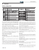
Service Manual 3 Troubleshooting (continued) Checking temperature sensors The pool heater temperature sensors (inlet and outlet water) are both resistance type devices. The following table shows the correct values for the sensors at various temperatures. Use an ohmmeter to read the resistance of the sensor at a known temperature. If the resistance of the sensor does not closely match, replace the sensor. Table 3B Inlet/Outlet System Sensor Resistance vs.
Service Manual 3 Troubleshooting Table 3C Troubleshooting Chart - Noisy System FAULT CAUSE CORRECTIVE ACTION - Supply gas problem. Natural gas pressures • Refer to Section 6 - Gas Connections of the EnergyRite should be between 4.0 inches w.c. and Installation and Operation Manual for detailed 14 inches w.c. LP gas pressures should information concerning the gas supply. be between 8.0 inches w.c. and 14 inches w.c. - Dirty / damaged burners.
Service Manual 3 Troubleshooting (continued) Table 3D Troubleshooting Chart - Fault Messages Displayed on Pool Heater Interface FAULT DESCRIPTION CORRECTIVE ACTION AUX Device 1 Open The field supplied safety wired into AUX Device 1 has opened. This will most commonly be a flow switch or low water cutoff. • Check pool heater pump operation on a call for heat. • Check for closed valves or obstructions in the pool heater piping.
Service Manual 3 Troubleshooting Table 3D (continued from previous page) Troubleshooting Chart - Fault Messages Displayed on Pool Heater Interface FAULT High Limit Open DESCRIPTION The outlet water temperature has • Verify that the system is full of water and that all air exceeded the fixed setting of the has been properly purged from the system. automatic reset high limit. • Verify that the pool heater is piped properly into the heating system.
Service Manual 3 Troubleshooting (continued) Table 3D (continued from previous page) Troubleshooting Chart - Fault Messages Displayed on Pool Heater Interface FAULT DESCRIPTION CORRECTIVE ACTION The pool heater has a call for heat, but there is insufficient water flow. • Verify that the system is full of water and that all air has been properly purged from the system. • Verify that the pool heater is piped properly into the heating system.
Service Manual 3 Troubleshooting Gas manifold pressure adjustment procedure NOTICE The gas valve is referenced to the fan pressurized chamber by a hose connected from the vent of the gas valve regulator to the chamber pressure tap located on the left side of the jacket. Reference the figures in this section for component location and connection points for pressure measurement.
Service Manual 3 Troubleshooting (continued) 16. The gas valve will open at the end of the trial for ignition stage and remain open as the burners fire. Observe the gas manifold pressure when valves open. If insufficient gas pressure is supplied to the burners, the burners will not fire. Record the gas pressure indicated on the manometer or magnahelic.
Service Manual 3 Troubleshooting Checking gas supply pressure 1. Turn the main power switch to the “OFF” position. 2. Shut off gas supply at the field installed manual gas cock in the gas piping to the appliance. If fuel supply is LP gas, shut off gas supply at the tank. 3. On ER152 - ER202 models remove the 1/8" hex plug, located on the “inlet” side of the gas valve. An inlet pressure tapping is located on the top side of the valve body (see FIG. 3-3).
Service Manual 3 Troubleshooting (continued) 13. Remove the manometer and related fittings from the “inlet” side of the gas valve, replace the 1/8" hex plug in the tee (Models ER252 - ER402) or gas valve (Models ER152 - ER202) and tighten. 14. Turn on the gas supply at the manual valve, turn on the LP gas at the tank if required. 15. Turn the power switch to the “ON” position. 16. Ensure that the “ON/OFF” knob or the valve is in the “ON” position. 17.
ERP-SER-Rev A CP-2M-3/07