Installation Instructions and Use & Care Guide RESIDENTIAL GAS WATER HEATERS 300 Maddox Simpson Parkway Lebanon, TN 37090 Phone: 615-889-8900 • Fax: 615-547-1000 Technical Services email: 2tech@lochinvar.com www.lochinvar.com FVIR GAS WATER HEATER (FLAMMABLE VAPOR IGNITION RESISTANT) FOR SPACE HEATING AND POTABLE WATER HEATING ONLY. NOT FOR USE IN MOBILE HOMES. This water heater complies with ANSI Z21.10.
TABLE OF CONTENTS Water Heater Safety .............................................................................................................................................................................. 1 Safe Installation, Use and Service ...................................................................................................................................................... 3 Safety Precautions ..........................................................................................
SAFE INSTALLATION, USE AND SERVICE Your safety and the safety of others is extremely important in the installation, use and servicing of this water heater. Many safety-related messages and instructions have been provided in this manual and on your water heater to warn you and others of a potential hazard. Read and obey all safety messages and instructions throughout this manual.
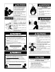
Fire or Explosion Harzard Do not store or use gasoline or other flammable vapors and liquids in the vicinity of this or any other appliance. Avoid all ignition sources if you smell Natural or LP gas. Do not expose water heater control to excessive gas pressure. Use only gas shown on rating plate. Maintain required clearances to combustibles. Keep ignition sources away from faucets after extended period of non-use. Read instruction manual before installing, using or servicing water heater.
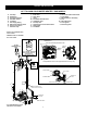
TYPICAL INSTALLATION GET TO KNOW YOUR WATER HEATER - GAS MODELS A B C D E F G H I Vent Pipe Draft Hood Anode (Not Shown) Hot Water Outlet Insulation Gas Supply Piping Manual Gas Shut-off Valve Ground Joint Union Sediment Trap J K L M N O P Q R Inner Door Outer Door Union Inlet Water Shut-off Valve Cold Water Inlet Inlet Dip Tube Temperature-Pressure Relief Valve Rating Plate Flue Baffle S T U V W X Y Gas Control Valve/Thermostat Drain Valve Manifold/Burner Assembly Flue Metal Drain Pan Piezo Igniter Ba
INSTALLING YOUR GAS WATER HEATER Important Information About This Water Heater Unpacking the Water Heater This gas water heater was manufactured to voluntary safety standards to reduce the likelihood of a flammable vapor ignition incident. New technology used in meeting these standards makes this product more sensitive to installation errors or improper installation environments.
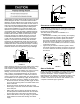
Location Requirements If flammable liquids or vapors have spilled or leaked in the area of the water heater, leave the area immediately and call the fire department from a neighbor’s home. Do not attempt to clean the spill until all ignition sources have been extinguished. WARNING Carbon Monoxide Poisoning Hazard WARNING Do not install in a mobile home. Doing so can result in carbon monoxide poisoning and death.
EXHAUST FAN REVERSE FLOW OF GASES IMPORTANT: The water heater should be located in an area where leakage of the tank or connections will not result in damage to the area adjacent to the water heater or to lower floors of the structure. Due to the normal corrosive action of water, the tank will eventually leak after an extended period of time. Also any external plumbing leak, including those from improper installation, may cause early failure of the tank due to corrosion if not repaired.
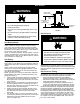
GAS SUPPLY WARNING Manual Gas Shut-off Valve Ground Joint Union Check with local utility for minimum height Explosion Hazard 3” Minimum • Use a new CSA approved gas supply line. • Install a shut-off valve. 6” Maximum Air Gap Sediment Trap • Do not connect a natural gas water heater to an L.P. gas supply. FIGURE 3. • Do not connect an L.P. gas water heater to a natural gas supply. Gas Pressure • Failure to follow these instructions can result in death, explosion, or carbon monoxide poisoning.
LP Gas Only Liquefied petroleum gas is over 50% heavier than air and in the occurrence of a leak in the system, the gas will settle at floor level. Basements, crawl spaces, closets and areas below ground level will serve as pockets for the accumulation of gas. Before lighting an L.P. gas water heater, smell all around the appliance at floor level. If you smell gas, follow the instructions as given in the warning on the front page. WARNING When your L.P.
COMBUSTION AIR & VENTILATION TABLE 3 WARNING BTUH Input Minimum Square Feet with 8’ Ceiling Vent must be installed by a qualified technician using the installation instructions. 30,000 188 9 x 21 45,000 281 14 x 20 Examples of a qualified technican include: gas technicians, authorized gas company personel, and authorized service persons.
fresh air can be taken from the outdoors or from crawl or attic spaces that freely communicate with the outdoors. Attic or crawl spaces cannot be closed and must be properly ventilated to the outside. 12” MAXIMUM Ductwork must be of the same cross-sectional area as the free area of the opening to which they connect. The minimum dimension of rectangular air ducts cannot be less than three inches.
GABLE VENT TO OUTDOORS ALTERNATIVE OPENING LOCATION INSTALL ABOVE INSULATION CONFINED SPACE 1 SQ. INCH CONFINED OUTLET AIR TO ATTIC 1 SQ. INCH PER 4000 BTUH PER 3000 BTUH SPACE INLET AIR FROM THE CRAWL SPACE ALTERNATE AIR INLET ALL AIR FROM OUTDOORS - USING A SINGLE PERMANENT OPENING 1 SQ. INCH PER 4000 BTUH FIGURE 8B.
Align the legs of the draft hood with the slots provided. Insert the legs and secure the draft hood to the water heater’s top with the four screws provided as shown in Figure 9. Do not alter the draft hood in any way. If you are replacing an existing water heater, be sure to use the draft hood supplied with this water heater. • • • Vent Pipe Size • It is important that you follow the guidelines in these instructions for sizing a vent pipe system.
LISTED VENT CAP 3 FT. MINIMUM WATER SYSTEM PIPING Piping Installation 2 FT. MINIMUM ABOVE ANY OBJECT WITHIN 10 FT. HORIZONTALLY Piping, fittings, and valves should be installed according to the installation drawing (Figure 13). If the indoor installation area is subject to freezing temperatures, the water piping must be protected by insulation. SUPPORT STRAP *MAINTAIN CLEARANCE TYPE B DOUBLE WALL VENT PIPE The water supply pressure should not exceed 80 psi.
IN A CLOSED SYSTEM, USE A THERMAL EXPANSION TANK COLD WATER SUPPLY TO FIXTURES HOT WATER OUTLET MAIN WATER SUPPLY PRESSURE REDUCING COLD WATER VALVE WITH BYPASS INLET VALVE (SHUT-OFF VALVE) UNION TEMPERATURE AND PRESSURE RELIEF VALVE DISCHARGE PIPE DO NOT CAP OR PLUG DRAIN LINE 3/4” ID MINIMUM 6” MAXIMUM AIR GAP 1” MINIMUM MASSACHUSSETTS: INSTALL A VACUUM RELIEF IN COLD WATER LINE PER FLOOR DRAIN SECTION 19 MGL 142. METAL DRAIN PAN 1 3/4” DEPTH MAXIMUM Closed System/Thermal Expansion FIGURE 13.
Temperature and Pressure Relief Valve • Explosion Harzard • 7HPSHUDWXUH SUHVVXUH UHOLHI YDOYH PXVW FRPSO\ ZLWK $16, = &6$ DQG $60( FRGH • T&P Relief Valve and Pipe Insulation (Some Models) 3URSHUO\ VL]HG WHPSHUDWXUH SUHVVXUH UHOLHI YDOYH PXVW EH LQVWDOOHG LQ RSHQLQJ SURYLGHG 1. Locate the temperature and pressure relief valve on the water heater (also known as a T&P relief valve). See Figure 15B. 2. Locate the slit running the length of the T&P relief valve insulation. 3.
• • • • • • • This water heater is not to be used as a replacement for an existing boiler installation. DOMSETIC HOT WATER OUT Do not use with piping that has been treated with chromates, boiler seal or other chemicals and do not add any chemicals to the water heater piping.
IMPORTANT INFORMATION ABOUT THIS WATER HEATER This gas water heater was manufactured to voluntary safety standards to reduce the likelihood of a flammable vapor ignition incident. The new technology used in meeting these standards makes this product more sensitive to installation errors. Please review the following checklist and make any required installation upgrades or changes.
OPERATING YOUR WATER HEATER Lighting Instructions WARNING Read and understand these directions thoroughly before attempting to light or re-light the pilot. Make sure the view port is not missing or damaged. (See Figure 23.) Make sure the tank is completely filled with water before lighting the pilot. Check the rating plate near the gas control valve/ thermostat for the correct type of gas. Do not use this water heater with any gas other than the one listed on the rating plate.
FOR YOUR SAFETY READ BEFORE LIGHTING WARNING: If you do not follow these instructions exactly, a fire or explosion may result causing property damage, personal injury or loss of life. FLAMMABLE BEFORE LIGHTING: ENTIRE SYSTEM MUST BE FILLED WITH WATER AND AIR PURGED FROM ALL LINES A. This appliance has a pilot which is lit by a piezo- C. Use only your hand to push in or turn the gas control knob. Never use tools. If the knob will not push in or electric spark gas ignition system.
Checking the Draft Water Temperature Regulation WARNING Water temperature over 125°F (52°C) can cause servere burns instantly resulting in severe injury or death. Burn Hazard Children, the elderly, and the physically or mentally disabled are at highest risk for scald injury. Do not touch vent. Doing so can result in burns. Feel water before bathing or showering.
Water Temperature °F Time for 1st Degree Burn (Less Severe Burns) 110 116 116 122 131 140 149 154 (normal shower temp.) (pain threshold) 35 minutes 1 minute 5 seconds 2 seconds 1 second Instantaneous Water Temperature Adjustment Time for Permanent Burns 2nd & 3rd Degree (Most Severe Burns) The water temperature setting can be adjusted from 55°F to 155°F. Turn the Gas Control/Temperature Knob to the desired setting/temperature.
Excessive condensation can cause pilot outage due to water running down the flue tube onto the main burner and putting out the pilot. A thermopile is used to determine if a pilot flame is present, and will shut off the gas supply to the main burner and the pilot if the flame is absent.
• • The majority of the rod’s diameter is less than 3/8”. Significant sections of the support wire (approx. 1/3 or more of the anode rod’s length) are visible. If the anode rod show signs of either or both it should be replaced. NOTE: Whether re-installing or replacing the anode rod, check for any leaks and immediately correct if EXPOSED SUPPORT found. WIRE In replacing the anode: 1. Turn off gas supply to the water heater. 2.
properly. To prevent water damage, the valve must be properly connected to a discharge line which terminates at an adequate drain. Standing clear of the outlet (discharged water may be hot), slowly lift and release the lever handle on the temperature and pressure relief valve to allow the valve to operate freely and return to its closed position. See Figure 21.
Replacing the Pilot/ Thermopile Assembly 1. 7. Route the new pilot tube, igniter wire and thermopile wire through the opening in the manifold door. See Figure 25. Remove the manifold door assembly as described in “Removing the Manifold/Burner Assembly” section. 8. Using the pilot screw removed earlier, attach the new pilot/thermopile assembly. Reattach the burner to the manifold using the screws removed earlier.
External Inspection & Cleaning of the Base-Ring Filter 1. Replacing the Manifold/Burner Assembly WARNING At least annually, check the base-ring filter (Figure 28) for any dust or debris that may have accumulated on the filter screen. NOTE: If the water heater is located in an area that is subjected to lint and dirt, it may be necessary to check the base-ring filter more frequently. 2.
7. Removing and Replacing the Gas Control Valve/Thermostat Connect the white (-) thermopile wire to the gas control valve/thermostat, then connect the red thermal switch wires to the thermal switch on the manifold door. (Figure 23). IMPORTANT: This water heater has a resettable thermal switch installed. Do not attempt to disable or modify this feature in any way. Use only factory authorized replacement parts. Removing the Gas Control Valve/Thermostat: 1.
FVIR System Operational Checklist 1. 2. 3. 4. 5. 6. 7. Manifold gasket properly sealed. Viewport not damaged or cracked. Flame-arrestor free of debris and undamaged. Manifold component block properly installed. No leaks at pilot and manifold connection. Manifold door screws securely tightened. Depress the button on the thermal switch TROUBLESHOOTING CHART PROBLEM BURNER WILL NOT IGNITE POSSIBLE CAUSE(S) 1. 2. 3. 4. 5.
PROBLEM SLOW HOT WATER RECOVERY POSSIBLE CAUSE(S) 1. Insufficient combustion air 2. Water heater flue or vent system blocked 3. Low gas pressure 4. Improper calibration 5. Base-Ring Filter blocked with lint/ dust 6. FVIR Flame Arrestor blocked with lint/dust. CORRECTIVE ACTION 1. Provide ventilation to water heater. Check flue way, flue baffle, and burner 2. Clean flue, locate source and correct 3. Check with gas utility company 4. Replace thermostat 5.
PILOT LIGHT TROUBLESHOOTING FLOWCHART Section A: Pilot light will not light (new installation). Section C: Pilot light will not remain lit. Is the manual gas shut-off valve, located in the supply line to the water heater, in the on position? YES Check for insufficient combustion air. Complete this section after completing Section B.
STATUS LIGHT AND DIAGNOSTIC CODE TROUBLESHOOTING CHART LED STATUS 0 FLASHES (LED NOT LIT) PROBLEM CORRECTIVE ACTION Pilot light is not lit or Thermopile has not yet reached normal operating temperature. Turn Gas Control Valve/Thermostat knob to OFF. Wait 10 minutes, then attempt to relight Pilot by following the lighting instructions on the water heater’s label. Until the Thermopile reaches its normal operating temperature, the Status Light will not blink, even if the Pilot is lit.
STATUS LIGHT AND DIAGNOSTIC CODE TROUBLESHOOTING CHART (Continued) LED STATUS PROBLEM CORRECTIVE ACTION 4 FLASHES The Gas Control Valve’s temperature sensor has detected that the water temperature was too high. Once this condition occurs, the Main Burner and the Pilot Light will be shut off. Since the Pilot light will be off, should this condition occur, this Flash Code will only be displayed immediately after the Pilot has been relit. Turn Gas Control Valve/ Thermostat knob to OFF.
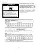
REPAIR PARTS ILLUSTRATION 1 When ordering repair parts, always give the following information: 1. 2. 3. 4. 3 Model, serial, and product number Type of gas Item number Parts description 2 4 5 6 8 Repair Parts List Item No.
Listed Parts Kits and Illustrations Item 11A: Pilot / Thermopile Assembly kit, which contains the pilot / pilot tube assembly, thermopile, and igniter electrode. (Natural Gas) Item 11B: Pilot / Thermopile Assembly kit, which contains the pilot / pilot tube assembly, thermopile, and igniter electrode. (L.P. Gas) Item 12A: Burner (Natural Gas/Low Nox) Item 12B: Burner (L.P.
NOTES 37
NOTES 38
NOTES 39
300 Maddox Simpson Parkway Lebanon, TN 37090 Phone: 615-889-8900 • Fax: 615-547-1000 Technical Services email: 2tech@lochinvar.com www.lochinvar.com Copyright © 2013 Lochinvar LLC. All rights reserved.