00275091_2000533998_Rev AC ™ FIRE TUBE Noble Fire Tube Boiler and Combi Installation & Service Manual NKC 110 - 199 & NKB 80 - 199 Series 100 - 101 & 110 - 111 ⚠ WARNING This manual must only be used by a qualified heating installer / service technician. Read all instructions in this manual before installing. Perform steps in the order given. Failure to comply could result in severe personal injury, death, or substantial property damage. Save this manual for future reference.
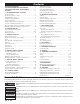
Contents HAZARD DEFINITIONS .............................................................. 2 PLEASE READ BEFORE PROCEEDING .......................... 3 THE NOBLE FIRE TUBE -- HOW IT WORKS ................... 4-5 RATINGS ........................................................................................... 6 1. DETERMINE BOILER LOCATION Provide Clearances .............................................................................. 7 Provide Air Openings to Room ........................................
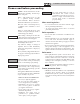
™ FIRE TUBE Installation & Service Manual Please read before proceeding ⚠WARNING Installer – Read all instructions, in this manual before installing. Perform steps in the order given. User – This manual is for use only by a qualified heating installer/ service technician. Refer to the User’s Information Manual for your reference. Have this boiler serviced/inspected by a qualified service technician, at least annually.
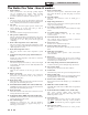
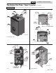
™ FIRE TUBE Installation & Service Manual The Noble Fire Tube - How it works... 1. Heat exchanger Allows system water to flow through specially designed coils for maximum heat transfer, while providing protection against flue gas corrosion. The coils are encased in a jacket that contains the combustion process. 2. Blower The blower pulls in air and gas through the venturi (item 5). Air and gas mix inside the blower and are pushed into the burner, where they burn inside the combustion chamber. 3.
Installation & Service Manual ™ FIRE TUBE The Noble Fire Tube - How it works... NOTICE (continued) The Noble Combi Boiler is shown throughout the manual unless otherwise noted.
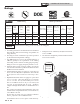
Installation & Service Manual ™ FIRE TUBE Ratings A S M E H LOW LEAD CONTENT Other Specifications AHRI Rating Model Number Note: Change “N” to “L” for L.P. gas models. Input MBH (Note 5) Heating Capacity MBH Net AHRI Ratings Water, MBH AFUE % SH Water Connections Boiler Water Content Gallons NPT = Combi Sweat = Boiler DHW Water Connections Combi Only Gas Connections Vent/Air Size (Note 4) Min Max (Note 2, 7) (Note 3, 7) (Note 1, 7) NKB80N 8.3 80 74 64 95.0 1.
™ FIRE TUBE 1 Determine boiler location Installation must comply with: • Local, state, provincial, and national codes, laws, regulations, and ordinances. • National Fuel Gas Code, ANSI Z223.1 – latest edition. • National Electrical Code. • For Canada only: B149.1 Installation Code, CSA C22.1 Canadian Electrical Code Part 1 and any local codes. NOTICE The Noble Fire Tube gas manifold and controls met safe lighting and other performance criteria when the boiler underwent tests specified in ANSI Z21.
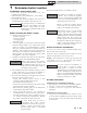
™ FIRE TUBE 1 Installation & Service Manual Determine boiler location Figure 1-1 Closet Installation - Minimum Required Clearances 1" MINIMUM CLEARANCE AROUND VENT PIPE For closet installations, CPVC, ⚠WARNING polypropylene, or stainless steel vent material MUST BE used in a closet structure due to elevated temperatures. Failure to follow this warning could result in fire, personal injury, or death.
™ FIRE TUBE 1 Determine boiler location NOTICE If you do not provide the recommended service clearances shown, it may not be possible to service the boiler without removing it from the space. Recommended clearances for service access - Front ............................................................................. 24" - Left ................................................................................ 12" - Right .............................................................................
™ FIRE TUBE 1 Installation & Service Manual Determine boiler location Table 1A Corrosive Contaminants and Sources Products to avoid: Spray cans containing chloro/fluorocarbons Permanent wave solutions Chlorinated waxes/cleaners Chlorine-based swimming pool chemicals Calcium chloride used for thawing Sodium chloride used for water softening Refrigerant leaks Paint or varnish removers Hydrochloric acid/muriatic acid Cements and glues Antistatic fabric softeners used in clothes dryers Chlorine-type bleache
™ FIRE TUBE 1 Determine boiler location Installation & Service Manual (continued) When removing a boiler from existing common vent system: ⚠ DANGER Do not install the Noble Fire Tube into a common vent with any other appliance. This will cause flue gas spillage or appliance malfunction, resulting in possible severe personal injury, death, or substantial property damage.
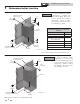
™ FIRE TUBE 2 Installation & Service Manual Prepare boiler Remove boiler from wood pallet 1. After removing the outer shipping carton from the boiler, remove the parts box. 2. To remove the boiler from the pallet: a. Remove the two (2) lag bolts securing the bottom of the unit to the pallet. b. Lift the boiler off the wall bracket mounted to the pallet (FIG. 2-1). CAUTION Do not attempt to use the water pipe fittings or gas pipe to lift the boiler.
™ FIRE TUBE 2 Prepare boiler ⚠WARNING (continued) After converting to LP, check combustion per the Start-up procedure in Section 10 of this manual. Failure to check and verify combustion could result in severe personal injury, death, or substantial property damage. Figure 2-2 Remove Natural Gas Venturi AIR SHUTTER DIR #2000534767 00 Figure 2-3 Gas Conversion Label Location 2. Mount the wall bracket using the 2 1/4" lag bolts provided. Make sure the top edge of the bracket is away from the wall.
™ FIRE TUBE 3 Installation & Service Manual General venting Direct venting options - Sidewall Vent DIR #2000534592 00 DIR #2000534593 00 Figure 3-1 Two-Pipe Sidewall Termination - See page 22 for more details Figure 3-2 PVC/CPVC Concentric Sidewall Termination - See page 25 for more details Direct venting options - Vertical Vent DIR #2000534588 00 DIR #2000534587 00 DIR #2000534590 00 Figure 3-3 Two-Pipe Vertical Figure 3-4 PVC/CPVC Concentric Figure 3-5 Vertical Vent, Sidewall Termination - See
™ FIRE TUBE 3 General venting Installation & Service Manual (continued) Install vent and combustion air piping The Noble Fire Tube must be vented and supplied with combustion and ventilation air as described in this section. Ensure the vent and air piping and the combustion air supply comply with these instructions regarding vent system, air system, and combustion air quality. See also Section 1 of this manual.
™ FIRE TUBE 3 Installation & Service Manual General venting Sizing The Noble Fire Tube uses model specific combustion air intake and vent piping sizes as detailed in Table 3A below. NOTICE Table 3A Air Intake/Vent Piping Sizes Model 2" Max Vent/Air 3" Max Vent/Air 80 - 110 100 feet 100 feet 150 60 feet 100 feet 199 N/A 100 feet Increasing or decreasing combustion air or vent piping sizes is not authorized unless otherwise specified in this manual.
™ FIRE TUBE 3 General venting Installation & Service Manual (continued) Optional room air NOTICE Optional room air is intended for commercial applications. Combustion air piping to the outside is recommended for residential applications. Commercial applications utilizing the Noble Fire Tube may be installed with a single pipe carrying the flue products to the outside while using combustion air from the equipment room.
™ 3 General PVC/CPVC: FIRE TUBE venting This product has been approved for use with the PVC/CPVC vent materials listed in Table 3D. Installing vent and air piping 1. 2. ⚠WARNING Use only the vent materials, primer, and cement specified in Table 3D to make the vent connections. Failure to follow this warning could result in fire, personal injury, or death. Use only cleaners, primers, and solvents that NOTICE are approved for the materials which are joined together.
Installation & Service Manual ™ FIRE TUBE 3 General venting (continued) Polypropylene: This product has been approved for use with polypropylene vent with the manufacturers listed in Table 3E. All terminations must comply with listed options in this manual and be a single-wall vent offering. For support and special connections required, see the manufacturer's instructions. All vent is to conform to standard diameter and equivalent length requirements established.
Installation & Service Manual ™ FIRE TUBE 3 General venting Stainless steel vent: Installation of a stainless steel vent system should adhere to the stainless steel vent manufacturer’s installation instructions supplied with the vent system. NOTICE This product has been approved for use with stainless steel using the manufacturers listed in Table 3G. ⚠WARNING NOTICE NOTICE Use only the materials, vent systems, and terminations listed in Tables 3G and 3H.
™ FIRE TUBE 4 Installation & Service Manual Sidewall direct venting Vent/air termination – sidewall Follow instructions below when ⚠WARNING determining vent location to avoid possibility of severe personal injury, death, or substantial property damage. ⚠WARNING A gas vent extending through an exterior wall shall not terminate adjacent to a wall or below building extensions such as eaves, parapets, balconies, or decks.
™ FIRE TUBE 4 Installation & Service Manual Sidewall direct venting Vent/air termination – sidewall Figure 4-2A Clearance to Gravity Air Inlets w/Field Supplied Fittings Figure 4-1C Alternate Venting Arrangement (if Space Allows) w/Field Supplied Fittings TO BOILER INTAKE AIR CONNECTION COUPLING 12” MIN 12” MIN FROM BOILER VENT PIPE CONNECTION BIRD SCREEN (TYPICAL) BIRD SCREEN BIRD SCREEN GRADE OR SNOW LINE 12” MIN 12” MIN ALTERNATE VENTING ARRANGEMENT (IF SPACE PERMITS) 12” MIN Figure 4-2B
™ FIRE TUBE 4 Sidewall direct venting (continued) Prepare wall penetrations 1. 2. 3. 4. 5. Installation & Service Manual Air pipe penetration: a. Cut a hole for the air pipe. Size the air pipe hole as close as desired to the air pipe outside diameter. Vent pipe penetration: a. Cut a hole for the vent pipe.
™ FIRE TUBE 4 Installation & Service Manual Sidewall direct venting Sidewall termination – optional concentric vent Description and usage The manufacturer offers optional concentric combustion air and vent pipe termination kits (Factory Kit #100140480 - 3" or #100140485 - 2"). Both combustion air and vent pipes must attach to the termination kit. The termination kit must terminate outside the structure and must be installed as shown below in FIG. 4-6.
™ FIRE TUBE 4 Sidewall direct venting Installation & Service Manual (continued) Sidewall termination – optional concentric vent models Figure 4-8 Concentric Vent Dimensional Drawing NOTICE Instead of cementing the smaller pipe to the rain cap, a field-supplied stainless steel screw may be used to secure the two (2) components together when field disassembly is desired for cleaning (see FIG. 4-9).
™ FIRE TUBE 4 Installation & Service Manual Sidewall direct venting Sidewall termination – optional concentric vent Figure 4-10 Concentric Vent Sidewall Attachment CAUTION DO NOT use field-supplied couplings to extend pipes. Airflow restriction will occur and may cause intermittent operation. 8. Cement appliance combustion air and vent pipes to the concentric vent termination assembly. See FIG. 4-10 for proper pipe attachment. 9.
™ FIRE TUBE 5 Installation & Service Manual Vertical direct venting Vent/air termination – vertical ⚠WARNING Follow instructions below when determining vent location to avoid possibility of severe personal injury, death or substantial property damage. Determine location Locate the vent/air terminations using the following guidelines: 1. The total length of piping for vent or air must not exceed the limits given in the General Venting Section on page 16 of this manual.
™ FIRE TUBE 5 Installation & Service Manual Vertical direct venting Vent/air termination – vertical Prepare roof penetrations 1. Air pipe penetration: a. Cut a hole for the air pipe. Size the air pipe hole as close as desired to the air pipe outside diameter. 2. Vent pipe penetration: a. Cut a hole for the vent pipe.
™ FIRE TUBE 5 Vertical direct venting Installation & Service Manual (continued) Vertical termination – optional concentric vent Description and usage The manufacturer offers an optional concentric combustion air and vent pipe termination kit. Both combustion air and vent pipes must attach to the termination kit. The termination kit must terminate outside the structure and must be installed as shown in FIG. 5-4. Field supplied pipe and fittings are required to complete the installation.
Installation & Service Manual ™ FIRE TUBE 5 Vertical direct venting Vertical termination – optional concentric vent ⚠WARNING Do not operate the appliance with the rain cap removed or recirculation of combustion products may occur. Water may also collect inside the larger combustion air pipe and flow to the burner enclosure. Failure to follow this warning could result in product damage or improper operation, personal injury, or death. CAUTION 6.
™ FIRE TUBE 5 Vertical direct venting Installation & Service Manual (continued) Alternate vertical concentric venting This appliance may be installed with a concentric vent arrangement where the vent pipe is routed through an existing unused venting system; or by using the existing unused venting system as a chase for vent and combustion air routing. Figure 5-8 Concentric Vent Example 1 FLUE EXHAUST Concentric Venting Arrangement SEAL The venting is to be vertical through the roof.
™ FIRE TUBE 5 Vertical direct venting Existing vent as a chase Follow all existing termination and clearance requirements and allowable pipe lengths. Use only approved venting materials listed in the General Venting Section of this manual. Figure 5-10 Existing Vent as a Chase FLUE EXHAUST AIR INLET WITH SCREEN SEAL EXISTING SEAL SEALED CAP DIR #2000534613 00 *For concept illustration only. Individual installations may vary due to job site specific equipment.
™ FIRE TUBE 6A Installation & Service Manual Hydronic piping System water piping methods The Noble Fire Tube is designed to function in a closed loop pressurized system not less than 12 psi (Non-metallic system piping must have an oxygen barrier to be considered a closed loop). A temperature and pressure gauge is included to monitor system pressure and outlet temperature and should be located on the boiler outlet.
™ FIRE TUBE 6A Installation & Service Manual Hydronic piping Near boiler piping components 2. Boiler circulating pump: On Combi units only, an integral boiler circulating pump is supplied by the factory. System piping must be sized to meet the minimum requirements in Table 6A on page 35.
™ FIRE TUBE 6A Hydronic piping Installation & Service Manual (continued) Figure 6-1 Pressure Drop vs. Flow_COMBI ONLY Table 6A Temperature Rise Applications_Combi Only NKC110 Delta T 19.1°F 20°F 25°F 30°F 35°F 40°F 45°F GPM 10.6 10.1 8.1 6.7 5.8 5.1 4.5 FT/HD 4.0 6.0 13.4 17.4 19.9 21.4 22.5 NKC150 Eq Ft of 1" Pipe 53 85 287 523 789 1085 1410 NKC199 FT/HD 4.0 9.6 13.1 Delta T 26.0°F 30°F 35°F 40°F 45°F GPM 10.6 9.2 7.9 6.9 6.1 FT/HD 4.0 9.6 14.1 17.0 19.
Installation & Service Manual ™ FIRE TUBE 6A Hydronic piping Figure 6-2 Single Boiler - Primary / Secondary Piping_COMBI ONLY PRESSURE REDUCING VALVE PRESSURE GAUGE BACKFLOW PREVENTER MAKE UP WATER SYSTEM SUPPLY SENSOR (OPTIONAL) AIR SEPARATOR MAY SUBSTITUTE LOW LOSS HEADER TO SYSTEM BALL VALVE (TYPICAL) FROM SYSTEM NOT TO EXCEED 4 PIPE DIA OR MAX.
Installation & Service Manual ™ FIRE TUBE 6A Hydronic piping (continued) Figure 6-3 Single Temperature Zoned with Circulators_COMBI ONLY ZONE #1 PRESSURE REDUCING VALVE PRESSURE GAUGE ZONE #2 ZONE #3 ZONE #4 BACKFLOW PREVENTER FLOW CHECK VALVE (TYPICAL) MAKE UP WATER SYSTEM SUPPLY SENSOR (OPTIONAL) ZONE CIRCULATORS (TYPICAL) AIR SEPARATOR EXPANSION TANK MAY SUBSTITUTE LOW LOSS HEADER BALL VALVE (TYPICAL) DRAIN POINT (TYPICAL) Y-STRAINER (RECOMMENDED) CHECK VALVE BOILER TEMPERATURE / PR
Installation & Service Manual ™ FIRE TUBE 6A Hydronic piping Figure 6-4 Multiple Boilers - Single Temperature Zoned with Circulators_COMBI ONLY Model 110 150 199 2 3 Number of Units 4 5 6 7 Required Pipe Sizes 8 1 1/2" 2" 2" 2 1/2" 2 1/2" 3" 3" 2" 2" 2 1/2" 3" 3" 3 1/2" 3 1/2" 2" 2 1/2" 3" 3" 3 1/2" 4" 4" ZONE #1 PRESSURE REDUCING VALVE TEMPERATURE / PRESSURE GAUGE ZONE #2 BACKFLOW PREVENTER ZONE #3 ZONE #4 MAKE UP WATER FLOW CHECK VALVE (TYPICAL) SYSTEM SUPPLY SENSOR (OPTIONAL) AIR SEPA
™ FIRE TUBE 6A Hydronic piping Installation & Service Manual (continued) Figure 6-5 Single Temperature Piped with Air Handler_COMBI ONLY AIR HANDLER AIR SEPARATOR BALL VALVE (TYPICAL) Y-STRAINER (RECOMMENDED) DRAIN POINT (TYPICAL) BOILER PRESSURE REDUCING VALVE TEMPERATURE / PRESSURE GAUGE PRESSURE GAUGE MAKE UP WATER BACKFLOW PREVENTER EXPANSION TANK UNION (TYPICAL) DIR #2000530076 00 NOTICE DHW piping omitted for clarity.
Installation & Service Manual ™ FIRE TUBE 6A Hydronic piping Figure 6-6 Pressure Drop vs. Flow_BOILER ONLY NK080 NK110 30.000 35.000 30.000 25.000 25.000 HEAD (ft) 20.000 HEAD (ft) 20.000 15.000 15.000 10.000 10.000 5.000 5.000 0.000 0.
™ FIRE TUBE 6A Hydronic piping Installation & Service Manual (continued) Figure 6-7 Single Boiler - Primary / Secondary Piping_BOILER ONLY PRESSURE REDUCING VALVE PRESSURE GAUGE BACKFLOW PREVENTER MAKE UP WATER SYSTEM SUPPLY SENSOR (OPTIONAL) AIR SEPARATOR MAY SUBSTITUTE LOW LOSS HEADER TO SYSTEM BALL VALVE (TYPICAL) FROM SYSTEM NOT TO EXCEED 4 PIPE DIA OR MAX.
Installation & Service Manual ™ FIRE TUBE 6A Hydronic piping Figure 6-8 Single Temperature Zoned with Circulators_BOILER ONLY ZONE #1 PRESSURE REDUCING VALVE PRESSURE GAUGE ZONE #2 ZONE #3 ZONE #4 BACKFLOW PREVENTER FLOW CHECK VALVE (TYPICAL) MAKE UP WATER SYSTEM SUPPLY SENSOR (OPTIONAL) ZONE CIRCULATORS (TYPICAL) AIR SEPARATOR EXPANSION TANK MAY SUBSTITUTE LOW LOSS HEADER BALL VALVE (TYPICAL) DRAIN POINT (TYPICAL) Y-STRAINER (RECOMMENDED) CHECK VALVE BOILER CIRCULATOR ANTI-SCALD VALVE WA
™ FIRE TUBE 6A Hydronic piping Installation & Service Manual (continued) Figure 6-9 Multiple Boilers - Single Temperature Zoned with Circulators_BOILER ONLY Model 80 110 150 199 2 Number of Units 3 4 5 6 7 Required Pipe Sizes 8 1 1/4" 1 1/2" 2" 2" 2 1/2" 2 1/2" 2 1/2" 1 1/2" 2" 2" 2 1/2" 2 1/2" 3" 3" 2" 2" 2 1/2" 3" 3" 3 1/2" 3 1/2" 2" 2 1/2" 3" 3" 3 1/2" 4" 4" ZONE #1 PRESSURE REDUCING VALVE TEMPERATURE / PRESSURE GAUGE ZONE #2 BACKFLOW PREVENTER ZONE #3 ZONE #4 MAKE UP WATER FLOW CHECK
™ FIRE TUBE 6A Installation & Service Manual Hydronic piping Figure 6-10 Single Temperature Piped Full Flow_BOILER ONLY PRESSURE GAUGE PRESSURE REDUCING VALVE BACKFLOW PREVENTER MAKE UP WATER AIR HANDLER AIR SEPARATOR EXPANSION TANK BALL VALVE (TYPICAL) Y-STRAINER (RECOMMENDED) DRAIN POINT (TYPICAL) BOILER CIRCULATOR ANTI-SCALD VALVE WATER HOT OUT DOMESTIC HOT WATER CIRCULATOR HMC COLD WATER IN BOILER TEMPERATURE / PRESSURE GAUGE INDIRECT DHW TANK UNION (TYPICAL) DIR #2000537261 00 NOTI
™ FIRE TUBE 6B Installation & Service Manual Domestic water piping (Combi Only) Scalding Water chemistry This combi heater can deliver scalding temperature water at any faucet in the system. Be careful whenever using hot water to avoid scalding injury. Certain appliances such as dishwashers and automatic clothes washers may require increased temperature water.
™ FIRE TUBE 6B Domestic water piping (Combi Only) Table 6E DHW Pressure Drop Chart DHW PRESSURE DROP Combi Sequence of operation The cold domestic water enters the plate heat exchanger through the DHW inlet connection, flow switch, and strainer. Cold water flows through the plate heat exchanger, where it is heated by hot boiler water, and then discharged through the Domestic Hot Water (DHW) outlet connection.
™ FIRE TUBE 6B Installation & Service Manual Domestic water piping (Combi Only) (continued) Figure 6-11 Combi DHW Piping BOILER EXPANSION TANK UNION (TYPICAL) PRESSURE RELIEF VALVE (REQUIRED, FIELD SUPPLIED) ASSE 1070 ANTI-SCALD MIXING VALVE (REQUIRED) H M C FLOW CHECK TEMPERATURE / PRESSURE GUAGE FLOW CONTROL VALVE HOT WATER SUPPLY COLD WATER SUPPLY DIR #2000534676 00 NOTICE Hydronic piping omitted for clarity.
™ FIRE TUBE 6B Installation & Service Manual Domestic water piping (Combi Only) Figure 6-12 DHW Recirculation w/Dedicated Return BOILER Note: Aquastat for DHW recirculation pump or thermostatic shut off valve must be used to stop recirculation water flow once the desired temperature has been reached. For best performance, Pre-Heat Mode should be enabled when using DHW recirculation.
Installation & Service Manual ™ FIRE TUBE 6B Domestic water piping (Combi Only) (continued) Figure 6-13 DHW Piping w/Recirculation Return Through Cold Line Note: Aquastat for DHW recirculation pump or thermostatic shut off valve must be used to stop recirculation water flow once the desired temperature has been reached. BOILER For best performance, Pre-Heat Mode should be enabled when using DHW recirculation.
™ FIRE TUBE 7 Installation & Service Manual Gas connections Connecting gas supply piping 1. Remove the front access panel and refer to FIG. 7-1 to pipe gas to the boiler. a. Install a field supplied sediment trap / drip leg upstream of the boiler gas controls. 2. Support piping with hangers, not by the boiler or its accessories. ⚠WARNING Figure 7-1 Gas Supply Piping The gas valve and blower will not support the weight of the piping.
Installation & Service Manual ™ FIRE TUBE 7 Gas connections ⚠WARNING (continued) Failure to apply pipe sealing compound as detailed in this manual can result in severe personal injury, death, or substantial property damage. ⚠WARNING Noble Fire Tubes are typically shipped ready to fire on natural gas. Check boiler rating plate to determine which fuel the boiler is set for. If set to natural gas, it may be converted to LP by installing an LP venturi (see page 12).
™ FIRE TUBE 7 Installation & Service Manual Gas connections Table 7A Natural Gas Pipe Size Chart Capacity of Schedule 40 Metallic Pipe in Cubic Feet of Natural Gas Per Hour (based on .60 specific gravity, 0.30" w.c.
™ FIRE TUBE 7 Gas connections (continued) 13. Shut off the gas supply at the manual gas valve in the gas piping to the appliance. 14. Remove the manometer from the pressure tap on top of the gas valve. Re-tighten the set screw inside the pressure tap. ⚠WARNING Installation & Service Manual When re-tightening the set screw, be sure to tighten securely to prevent gas leaks. Do not check for gas leaks with an open flame -- use the bubble test.
Installation & Service Manual ™ FIRE TUBE 8 Field wiring NOTICE ⚠WARNING NOTICE For field wiring on Combi units, reference the Combi Installation and Service Manual provided with the unit. ELECTRICAL SHOCK HAZARD – For your safety, turn off electrical power supply before making any electrical connections to avoid possible electric shock hazard. Failure to do so can cause severe personal injury or death. Wiring must be N.E.C. Class 1.
™ FIRE TUBE 8 Field wiring Installation & Service Manual (continued) Thermostat (field supplied) System supply sensor 1. Connect the room thermostat or end switch (isolated contact only) to the room thermostat as shown in FIG.'s 8-4 and 8-5. 2. Install the thermostat on the inside wall, away from influences of drafts, hot or cold water pipes, lighting fixtures, televisions, sunlight or fireplaces. 3. Thermostat anticipator (if applicable): a. If connected directly to boiler, set for 0.1 amps. b.
DIR #2000537237 00 COM NO ROOM THERMOSTAT (FIELD SUPPLIED) AUXILIARY LIMIT (FIELD SUPPLIED) ™ FLOW SWITCH (FIELD SUPPLIED) LOW WATER CUT OFF (OPTIONAL) SYSTEM SUPPLY SENSOR 8 OUTDOOR SENSOR FIRE TUBE Installation & Service Manual Field wiring Figure 8-4 Low Voltage Field Wiring Connections_BOILER ONLY
DIR #2000561794 00 ROOM THERMOSTAT (FIELD SUPPLIED) ™ AUXILIARY LIMIT (FIELD SUPPLIED) LOW WATER CUT OFF (OPTIONAL) Field wiring SYSTEM SUPPLY SENSOR 8 OUTDOOR SENSOR FIRE TUBE Installation & Service Manual (continued) Figure 8-5 Low Voltage Field Wiring Connections_COMBI ONLY 57
™ FIRE TUBE 9 Installation & Service Manual Condensate disposal Condensate drain NOTICE Use materials approved by the authority having jurisdiction. In the absence of other authority, PVC and CPVC pipe must comply with ASTM D1785 or D2845. Cement and primer must comply with ASME D2564 or F493. For Canada use CSA or ULC certified PVC or CPVC pipe, fittings, and cement.
™ FIRE TUBE 10 Start-up Pre-Commissioning Cleaning 1. Prior to fill and start-up, flush the entire heating system. 2. Clean the entire heating system with an approved precommissioning cleaner (comparable to Sentinel X300 or Fernox F3) in accordance with the manufacturer’s recommendation to remove debris and prolong the life of the heat exchanger. 3. Clean all water filtering devices in the system. 4. Flush the cleaning solution out of the entire system and refill.
™ FIRE TUBE 10 Installation & Service Manual Start-up 1. Use glycol only if needed for freeze protection fluid. Fill and test water system 2. Propylene glycol is the recommended freeze protection fluid. 1. Fill system only after ensuring the water meets the requirements of this manual. 3. Make sure to flush the boiler system before adding glycol. 4. Determine the freeze protection fluid quantity using system water content, following the fluid manufacturer's instructions.
™ FIRE TUBE 10 Start-up (continued) Check for gas leaks Before starting the boiler, and during initial operation, smell near the floor and around the boiler for gas odorant or any unusual odor. Remove the front access panel and smell the interior of the boiler enclosure. Do not proceed with startup if there is any indication of a gas leak. Use an approved leak detection solution. Repair any leaks at once. ⚠WARNING DO NOT adjust gas valve outlet pressure.
™ FIRE TUBE 10 Installation & Service Manual Start-up Final checks before starting the boiler Check gas piping Read this manual to familiarize yourself with boiler control module operation. Reference page 63 for proper steps to start boiler. 1. Check around the boiler for gas odor following the procedure on page 63 of this manual. Verify the boiler and system are full of water and all system components are correctly set for operation.
™ FIRE TUBE 10 Start-up Installation & Service Manual (continued) Figure 10-2 Operating Instructions Move switch to the “OFF” position.
™ FIRE TUBE 10 Installation & Service Manual Start-up Noble Fire Tube control module Use the control panel (FIG. 10-3) to set temperatures, operating conditions, and monitor boiler operation. Figure 10-3 Control Panel RESET BUTTON DISPLAY WINDOW - Indicates that the unit has a Space Heating demand. - Indicates that the unit has a DHW demand. Note: This icon will flash if the unit has a Pre-heat demand (if enabled). (Combi Only) UP BUTTON - Indicates that the boiler pump is running.
™ FIRE TUBE 10 Start-up (continued) Setup wizard - MAX SH SETPT • The Noble Fire Tube control has a Setup Wizard feature that can be used to help with the initial start-up of the unit. This Setup Wizard will walk an installer through the most commonly required parameters. The Setup Wizard is automatically accessed the first time the unit is powered up from the factory and will allow setting of certain parameters without the need to enter the installer password.
™ FIRE TUBE 10 - - - - Installation & Service Manual Start-up DHW SETPT • This is the desired set point temperature of Domestic Hot Water (DHW) generated by the unit. Note that the required anti-scald mixing valve will likely require a setting greater than the desired DHW temperature. • Range: 60°F – MAX DHW SETPT • Default: 120°F DOMESTIC HOT WATER BOILER WATER TEMP (BOILER ONLY) • This is the desired temperature of the boiler water going to the indirect tank.
™ FIRE TUBE 10 Start-up Installation & Service Manual (continued) 3. Press the ► and ▼ buttons (simultaneously) for 5 seconds to enter Service Mode. Verify space heat circulator operation 4. Insert the probe from a combustion analyzer into the hole on the vent adapter. The Space Heating Mode controls the boiler pump and the diverter valve.
™ FIRE TUBE 11 Installation & Service Manual Operating information General Parameters in the set points menu: How the boiler operates - The Noble Fire Tube uses an advanced stainless steel heat exchanger and electronic control module that allows fully condensing operation. The blower pulls in air and pushes flue products out of the boiler through the heat exchanger and flue piping. The control module regulates blower speed to control the boiler firing rate.
™ FIRE TUBE 11 Operating information Installation & Service Manual (continued) Enter the installer password Parameters in the installer menu: To enter the installer password, use the ▲ and ▼ buttons to change the value of the first digit to 5, then press ► to move to the next digit. Repeat this process to fill in the remaining digits and enter the password 5-3-0-9. Once the final digit has been entered, press the ► button to access the installer menu.
™ FIRE TUBE 11 Installation & Service Manual Operating information DHW Priority (Boiler) Combi diverter valve (Combi Only) The Smart System control allows the connection of a DHW thermostat or tank sensor to the low voltage board. When a tank sensor is connected, the DHW thermostat input is ignored. The control will attempt to satisfy a DHW call before a concurrent space heating call; however, the unit will switch between SH and DHW calls according to the settings SH/DHW SW Time and DHW/SH SW Time.
™ FIRE TUBE 11 Operating information Installation & Service Manual (continued) Outdoor air reset Outdoor Air Shutdown The Noble Fire Tube uses an advanced non-linear outdoor reset curve to improve system efficiency by reducing the boiler water set point as the outdoor temperature warms up.
™ FIRE TUBE 11 Operating information Cascade When multiple Noble Fire Tubes are installed, they can be wired together in a Cascade sequence. A maximum of eight (8) boilers can be controlled from a single control. In this application one boiler would be designated as the Leader control and all others would be designated as Member controls. The Leader control can be programmed to use Lead/ Lag or Efficiency Optimization control methods. Noble Fire Tubes can only control Space Heating demands in Cascade.
™ FIRE TUBE 11 Operating information Installation & Service Manual (continued) Low voltage blocking The blower and gas valve require a minimum amount of voltage in order to operate properly. If an ignition attempt is made when the line voltage is temporarily low (such as during a brownout), the control could enter a manual reset lockout. To prevent this, the control monitors the voltage and blocks any heat demands until the voltage returns to an acceptable level.
™ FIRE TUBE 11 Installation & Service Manual Operating information Sequence of operation OPERATION 1. Upon a call for heat, the control turns on the appropriate pumps. The LWCO must close. 2. Once the LWCO has closed, the auxiliary limit switch must close. 3. The control starts the pre-purge cycle by initiating the blower. 4. The control starts the trial for ignition by firing the spark electrode and opening the gas valve. 5.
™ FIRE TUBE 11 Operating information Installation & Service Manual (continued) Sequence of operation (continued) OPERATION DISPLAY 6. If flame is detected, it holds the firing rate steady for a few seconds to let the flame stabilize, then it begins to modulate the firing rate based on a set point or some other command. 7.
™ FIRE TUBE 12 Installation & Service Manual Maintenance Maintenance and annual startup Table 12A Service and Maintenance Schedules Owner maintenance Service technician (see the following pages for instructions) (see the Noble Fire Tube User’s Information Manual for instructions) ANNUAL START-UP General: • Address reported problems • Inspect interior; clean and vacuum if necessary; • Clean condensate trap • Check for leaks (water, gas, flue, condensate) • Verify flue and air lines in good conditio
™ 12 FIRE TUBE Maintenance Installation & Service Manual (continued) Follow the Service and maintenance procedures given throughout this manual and in component literature ⚠WARNING shipped with the boiler. Failure to perform the service and maintenance could result in damage to the boiler or system. Failure to follow the directions in this manual and component literature could result in severe personal injury, death, or substantial property damage.
™ FIRE TUBE 12 Maintenance Check fill water meter 1. Check fill water meter for water usage. If the amount exceeds 5% of your system volume, you could have a leak. Have the system checked for leaks and fixed by a qualified service technician. Test boiler water 1. Test boiler water. Reference the Noble Installation and Service Manual for guidelines. When test indicates, clean system water with approved system restorer following the manufacturer’s information. Check boiler relief valve 1.
™ FIRE TUBE 12 Maintenance Installation & Service Manual (continued) Handling ceramic fiber materials Figure 12-2 Burner Assembly REMOVAL OF COMBUSTION CHAMBER LINING TOP PLATE ⚠WARNING GASKET BURNER DIR #2000534736 00 Check flame signal 1. At high fire the flame signal shown on the display should be at least 10 microamps. 2. A lower flame signal may indicate a fouled or damaged ignition / flame sense electrode.
™ FIRE TUBE 12 Maintenance Cleaning the boiler heat exchanger 1. Shut down boiler: • Follow the “To Turn Off Gas to Appliance” instructions for the boiler in Section 10 - Startup of the Lochinvar Combi Boiler Installation and Operation Manual. • Do not drain the boiler unless it will be exposed to freezing temperatures. If using freeze prevention fluids in the system, do not drain. 2. Allow time for the boiler to cool to room temperature if it has been firing. 3. Remove the front access panel. 4.
™ FIRE TUBE 12 Maintenance Installation & Service Manual (continued) Figure 12-3 Remove flow sensor and DHW flow switch assembly 3. Allow the unit to progress through its normal diagnostics and pre-purge programming. 4. Allow the unit to fire and operate until the temperatures stabilize. This occurs when the inlet and outlet temperatures are rising together and the Delta T (T) is maintained. 5.
Installation & Service Manual ™ FIRE TUBE 13 Troubleshooting If this boiler may be frozen, ⚠ DANGER immediately shut off power and gas to the appliance and contact the factory for further instructions. Operation when the heat exchanger, internal pipes, or pressure relief valves are frozen, will result in internal pressure build-up and a deadly steam explosion. Neither the Freeze Protection feature of the boiler control module nor the use of glycol eliminates the possibility of freezing.
™ FIRE TUBE 13 Troubleshooting Installation & Service Manual (continued) Checking temperature sensors The boiler temperature sensors (inlet water, outlet water, system water, flue, and outdoor air) are all resistance type devices. The following tables show the correct values for the sensors at various temperatures. Use an ohmmeter to read the resistance of the sensor at a known temperature.
™ FIRE TUBE 13 Installation & Service Manual Troubleshooting Table 13-2 Troubleshooting Chart - Noisy System FAULT CAUSE CORRECTIVE ACTION Supply gas problem. Natural gas • Refer to Section 7 - Gas Connections pressures should be between 4 inches w.c. detailed information concerning the gas supply. and 14 inches w.c. LP gas pressures should be between 8 inches w.c. and 14 inches w.c. Gas/air mixture problem. N˘˒˜ˢ O˙ˎ˛ˊ˝˒˘˗ Dirty/damaged burner.
™ FIRE TUBE 13 Troubleshooting Installation & Service Manual (continued) Table 13-3 Troubleshooting Chart - Fault Messages Displayed on Boiler Interface FAULT Mˎ˖˘˛ˢ E˛˛˘˛ DESCRIPTION The control module has detected parameter settings that are corrupted. CORRECTIVE ACTION • Replace control module. • Vent/air intake lengths exceed the maximum allowed lengths. Refer to Section 3 - General Venting for proper lengths. Fˊ˗ S˙ˎˎˍ (will require a manual reset once the condition has been corrected.
™ FIRE TUBE 13 Installation & Service Manual Troubleshooting Table 13-3 (continued from previous page) Troubleshooting Chart - Fault Messages Displayed on Boiler Interface FAULT DESCRIPTION CORRECTIVE ACTION • Adjust the set point of the auto reset limit to a higher setting up to a maximum of 200°F. Reference Section 11 - Operating Information for adjusting procedures. • Verify that the system is full of water and that all air has been properly purged from the system.
™ FIRE TUBE 13 Troubleshooting Installation & Service Manual (continued) Table 13-3 (continued from previous page) Troubleshooting Chart - Fault Messages Displayed on Boiler Interface FAULT DESCRIPTION CORRECTIVE ACTION • Inspect spark electrode and associated wiring for damage and connection. Reference page 78 of this manual for removal and cleaning procedures. Replace if necessary. • Check for proper electrical grounding of the unit.
™ FIRE TUBE 13 Installation & Service Manual Troubleshooting Table 13-3 (continued from previous page) Troubleshooting Chart - Fault Messages Displayed on Boiler Interface FAULT DESCRIPTION The stack temperature has exceeded the F˕˞ˎ Tˎ˖˙ L˒˖˒˝ Flue Temp Limit set parameters. CORRECTIVE ACTION • Inspect the heat exchanger. Reference page 80 of this manual for the procedure on how to clean the flue side of the heat exchanger. • Inspect the flue sensor and associated wiring.
™ FIRE TUBE 13 Troubleshooting Installation & Service Manual (continued) Table 13-3 (continued from previous page) Troubleshooting Chart - Fault Messages Displayed on Boiler Interface FAULT DESCRIPTION O˞˝˕ˎ˝ Sˎ˗˜˘˛ Fˊ˞˕˝ (will require a manual reset once the condition One or both of the outlet sensors has opened or shorted. has been corrected. Press the RESET button on the display to reset.) CORRECTIVE ACTION • Check the sensor and its associated wiring.
Installation & Service Manual ™ FIRE TUBE 13 Troubleshooting Table 13-3 (continued from previous page) Troubleshooting Chart - Fault Messages Displayed on Boiler Interface ERROR CODE DESCRIPTION CORRECTIVE ACTION • Check 120 vac supply to the transformer. L˘ˠ V˘˕˝ˊːˎ 120 vac input to the main control board has dropped below 80 vac. • Check wiring connections at the low voltage terminal strip. • Check the wire size/length to remote devices. • Replace the transformer. • Check 24V.
™ FIRE TUBE 13 Troubleshooting Installation & Service Manual (continued) Table 13-3 (continued from previous page) Troubleshooting Chart - Fault Messages Displayed on Boiler Interface FAULT CAUSE CORRECTIVE ACTION • Verify DHW flow is at least 0.4 gpm. DHW flow switch is not triggering a DHW demand (red light on flow switch sensor does not turn on during a DHW draw). • Check wiring harness connections between the low voltage connection board connector CN4 and the flow switch sensor.
™ FIRE TUBE 13 Installation & Service Manual Troubleshooting Table 13-3 (continued from previous page) Troubleshooting Chart - Fault Messages Displayed on Boiler Interface FAULT CAUSE A DHW demand is present. C˘˖ˋ˒ B˘˒˕ˎ˛ ˒˜ R˞˗˗˒˗ː ˋ˞˝ D˘ˎ˜ N˘˝ S˞˙˙˕ˢ Hˎˊ˝ˎˍ Wˊ˝ˎ˛ ˝˘ S˙ˊˌˎ Hˎˊ˝˒˗ː Sˢ˜˝ˎ˖ (C˘˖ˋ˒ O˗˕ˢ) CORRECTIVE ACTION • Wait until DHW demand has ended, then combi unit should provide heated water to the space heating system. The Noble Fire Tube does not provide heated water during a DHW demand.
Installation & Service Manual ™ FIRE TUBE 13 Troubleshooting (continued) Combustion Analysis Procedure ⚠WARNING 1. Turn the main power off to the boiler. 2. Hold the ► plus the▼ button for five (5) seconds to enter Service Mode. 3. Once the boiler has modulated up to full fire, measure the combustion. Place the analyzer probe in the fitting on the flue adapter. The values should be in the range listed in Table 13-4. The CO levels shall be less than 200 ppm for a properly installed unit.
™ FIRE TUBE 13 Installation & Service Manual Troubleshooting Figure 13-2 Gas Valve Adjustment_Layout 1 SCREW CAP MUST BE REMOVED TO ACCESS BIAS/OFFSET ADJUSTMENT SCREW THROTTLE ADJUSTMENT SCREW (REQUIRES 2.
Installation & Service Manual ™ FIRE TUBE 14 Diagrams Figure 14-1 Combi Models Only: Ladder Diagram (Standard) 120VAC NEUTRAL JUNCTION BOX 120V SUPPLY "L" GROUND 120V SUPPLY "N" INTEGRATED CONTROL X1-6 F1 SYSTEM PUMP RELAY X1-2 6.3A F2 SYSTEM PUMP "L" SYSTEM PUMP X1-4 BOILER PUMP RELAY X1-1 1 3.15A BLOWER 0.
Installation & Service Manual ™ FIRE TUBE 14 Diagrams Figure 14-2 Combi Models Only: Wiring Diagram (Standard) DISPLAY LOW VOLTAGE 120 VAC HIGH VOLTAGE INTEGRATED CONTROL CONNECTION BOARD CN1 1 2 3 4 5 6 7 8 9 10 SHIELD A CASCADE X-7 B SHIELD SYSTEM SENSOR OUTDOOR SENSOR JUNCTION BOX X1-3 X1-2 BOX DEPICTS OPTONAL ITEMS PR SYSTEM PUMP G CN5 L GND X6 N X1-6 X1-5 BK W X1-8 X1-4 G BR X1-1 R 120V SUPPLY G BOILER PUMP TRANSFORMER 24 VAC LOW WATER CUT OFF COM CN6-1 CN6-2 CN6-3
Installation & Service Manual ™ FIRE TUBE 14 Diagrams (continued) Figure 14-3 Boiler Models Only: Ladder Diagram (Standard) 120VAC NEUTRAL JUNCTION BOX 120V SUPPLY "L" GROUND 120V SUPPLY "N" INTEGRATED CONTROL X1-6 SYSTEM PUMP RELAY X1-2 6.3A DHW PUMP X1-3 DHW PUMP "L" X1-4 BOILER PUMP "L" BOILER PUMP RELAY BOILER PUMP RELAY F2 BOILER PUMP 1 BLOWER 24VDC SUPPLY 2 3 X1-8 F3 0.8A DHW PUMP X1-1 3.
Installation & Service Manual ™ FIRE TUBE 14 Diagrams Figure 14-4 Boiler Models Only: Wiring Diagram (Standard) DISPLAY LOW VOLTAGE 120 VAC HIGH VOLTAGE CONNECTION BOARD JUNCTION BOX CN1 1 2 3 4 5 6 7 8 9 10 SHIELD A CASCADE B SHIELD TANK SENSOR SYSTEM SENSOR OUTDOOR SENSOR X-7 X1-3 OR X1-4 BR X1-2 PR BOX DEPICTS OPTONAL ITEMS DHW PUMP G BOILER PUMP G SYSTEM PUMP G CN5 L GND X6 N X1-6 X1-5 BK W X1-8 G X1-1 R 120V SUPPLY G TRANSFORMER 24 VAC LOW WATER CUT OFF COM CN
™ FIRE TUBE Installation & Service Manual Notes 99
Revision A (PCP #3000004508 / CN #500004666) initial release. Revision B (PCP #3000005203 / CN #500005353) reflects the addition of the DHW flow switch filter cleaning section and the Noble logo. Revision C (PCP #3000005203 / CN #500005353) reflects updates made to the mixing valve statements. Revision D (PCP# 3000006133 / CN# 500007549) reflects the addition of PVC-DWV vent fitting in Table 3D on page 18.