WH-I-O Rev H Installation & Operation Manual Models: WH 55 - 399 WARNING This manual must only be used by a qualified heating installer / service technician. Read all instructions, including this manual and the Knight Wall Mount Service Manual, before installing. Perform steps in the order given. Failure to comply could result in severe personal injury, death, or substantial property damage. Save this manual for future reference.
Contents HAZARD DEFINITIONS . . . . . . . . . . . . . . . . . . . . . . . . . . 2 PLEASE READ BEFORE PROCEEDING . . . . . . . . . . . . 3 THE KNIGHT WALL MOUNT BOILER-- HOW IT WORKS . 4-5 RATINGS . . . . . . . . . . . . . . . . . . . . . . . . . . . . . . . . . . . . . . 6 1. DETERMINE BOILER LOCATION Provide Clearances . . . . . . . . . . . . . . . . . . . . . . . . . . . . . . 7 Provide Air Openings to Room . . . . . . . . . . . . . . . . . . . . . 9 Wall Mounting Location . . . . . . . . . . . . . . . .
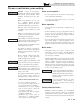
Installation & Operation Manual Please read before proceeding WARNING Installer – Read all instructions, including this manual and the Knight Wall Mount Service Manual, before installing. Perform steps in the order given. User – This manual is for use only by a qualified heating installer/ service technician. Refer to the User’s Information Manual for your reference. Have this boiler serviced/inspected by a qualified service technician, at least annually.
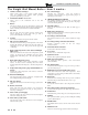
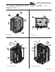
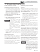
Installation & Operation Manual The Knight Wall Mount Boiler - How it works... 1. Stainless steel heat exchanger Allows system water to flow around specially designed tubes for maximum heat transfer, while providing protection against flue gas corrosion. 2. Combustion chamber access cover Allows access to the combustion side of the heat exchanger. 3. 4. Blower 8. 18. High voltage junction box Venturi Flue gas sensor (limit rated) Allows for the connection of the PVC air intake pipe to the boiler.
Installation & Operation Manual The Knight Wall Mount Boiler - How it works...
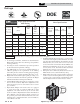
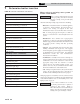
Installation & Operation Manual Ratings A S M E H Knight Wall Mount Boiler AHRI Rating Input MBH Model Number Note: Change “N” to “L” for L.P. gas models. Heating Capacity MBH Net AHRI Ratings Water, MBH (Note 5) Other Specifications AFUE % Boiler Water Water Gas Content Connections Connections Gallons Vent/Air Size (Note 4) Min Max (Note 2, 8) (Note 3, 8) (Note 1, 8) WHN055 11 55 51 44 96 2.5 1" 1/2" 2" WHN085 17 85 79 69 96 2.
Installation & Operation Manual 1 Determine boiler location Installation must comply with: WARNING This appliance is certified as an indoor appliance. Do not install the appliance outdoors or locate where the appliance will be exposed to freezing temperatures or to temperatures that exceed 100°F. Do not install the appliance where the relative humidity may exceed 93%.
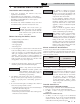
Installation & Operation Manual 1 Determine boiler location Figure 1-1 Closet Installation - Minimum Required Clearances WARNING TOP 6" MINIMUM LEFT 0" MINIMUM * VENTILATING AIR OPENING 6" For closet installations, CPVC, polypropylene or stainless steel vent material MUST BE used in a closet structure due to elevated temperatures. Failure to follow this warning could result in fire, personal injury, or death.
Installation & Operation Manual 1 Determine boiler location (continued) Provide air openings to room: Residential garage installation Knight wall mount boiler alone in boiler room Precautions 1. No air ventilation openings into the boiler room are needed when clearances around the Knight wall mount boiler are at least equal to the SERVICE clearances shown in FIG.’s 1-1 and 1-2. For spaces that do NOT supply this clearance, provide two openings as shown in FIG. 1-1.
Installation & Operation Manual 1 Determine boiler location Table 1A Corrosive Contaminants and Sources Products to avoid: Spray cans containing chloro/fluorocarbons Permanent wave solutions Chlorinated waxes/cleaners Chlorine-based swimming pool chemicals Calcium chloride used for thawing Sodium chloride used for water softening Refrigerant leaks Paint or varnish removers Hydrochloric acid/muriatic acid Cements and glues Antistatic fabric softeners used in clothes dryers Chlorine-type bleaches, detergen
Installation & Operation Manual 1 Determine boiler location (continued) When removing a boiler from existing common vent system: DANGER Do not install the Knight wall mount boiler into a common vent with any other appliance. This will cause flue gas spillage or appliance malfunction, resulting in possible severe personal injury, death, or substantial property damage.
Installation & Operation Manual 2 Prepare boiler Remove boiler from wood pallet Table 2A LP Conversion Table LP Conversion Table Model LP Orifice Stamping 55 055 85 085 110 110 155 155 199 199 285 H285 399 8.0 1. After removing the outer shipping carton from the boiler, remove the parts box. 2. To remove the boiler from the pallet: a. Remove the two (2) lag bolts securing the bottom of the unit to the pallet. b. Lift the boiler off the wall bracket mounted to the pallet. 3.
Installation & Operation Manual 2 Prepare boiler (continued) 13. Reattach the Molex plug to the gas valve. 14. Models 55 - 285 only, turn the gas valve power switch to the “ON” position. 15. Model 399 only, turn on power at the source. 16. After the installation is complete, fill out the gas conversion label (in the conversion kit bag) and affix it to the unit under the boiler rating plate inside the unit.
Installation & Operation Manual 3 General venting Direct venting options - Sidewall Vent Figure 3-1 Two-Pipe Sidewall Termination - See page 22 for more details Figure 3-3 Two-Pipe Vertical Termination - See page 29 for more details 14 Figure 3-2 PVC/CPVC Concentric Sidewall Termination - See page 26 for more details Figure 3-4 PVC/CPVC Concentric Vertical Termination - See page 30 for more details Figure 3-5 Vertical Vent, Sidewall Air - See page 18 for more details
Installation & Operation Manual 3 General venting Install vent and combustion air piping DANGER WARNING The Knight wall mount boiler must be vented and supplied with combustion and ventilation air as described in this section. Ensure the vent and air piping and the combustion air supply comply with these instructions regarding vent system, air system, and combustion air quality. See also Section 1 of this manual.
Installation & Operation Manual 3 General venting Requirements for installation in Canada Note: The minimum combustion air and vent piping length is 12 equivalent feet. 1. When determining equivalent combustion air and vent length, add 5 feet for each 90° elbow and 3 feet for each 45° elbow. 2. 3. 4. Installations must be made with a vent pipe system certified to ULC-S636. The first three (3) feet of plastic vent pipe from the appliance flue outlet must be readily accessible for visual inspection.
Installation & Operation Manual 3 General venting (continued) Materials Air inlet pipe materials: The air inlet pipe(s) must be sealed. Choose acceptable combustion air inlet pipe materials from the following list: PVC, CPVC, Polypropylene or ABS Dryer Vent or Sealed Flexible Duct (not recommended for rooftop air inlet) Galvanized steel vent pipe with joints and seams sealed as specified in this section. Type “B” double-wall vent with joints and seams sealed as specified in this section.
Installation & Operation Manual 3 General venting Optional room air NOTICE Optional room air is intended for commercial applications. Combustion air piping to the outside is recommended for residential applications. Commercial applications utilizing the Knight wall mount boiler may be installed with a single pipe carrying the flue products to the outside while using combustion air from the equipment room.
Installation & Operation Manual 3 General venting (continued) PVC/CPVC 1. This product has been approved for use with the PVC/CPVC vent materials listed in Table 3D. Installing vent and air piping WARNING The vent connection to the appliance must be made with the starter piece provided with the appliance if PVC/CPVC vent is to be used. The field provided vent fittings must be cemented to the CPVC pipe section using an “All Purpose Cement” suitable for PVC and CPVC pipe.
Installation & Operation Manual 3 General venting Polypropylene WARNING This product has been approved for use with polypropylene vent with the manufacturers listed in Table 3E. All terminations must comply with listed options in this manual and be a single-wall vent offering. For use of flex pipe, it is recommended to have the vent material in 32°F or higher ambient space before bending at installation.
Installation & Operation Manual 3 General venting (continued) Stainless steel vent NOTICE This product has been approved for use with stainless steel using the manufacturers listed in Table 3G. WARNING Use only the materials, vent systems, and terminations listed in Tables 3G and 3H. DO NOT mix vent systems of different types or manufacturers. Failure to comply could result in severe personal injury, death, or substantial property damage.
Installation & Operation Manual 4 Sidewall direct venting Vent/air termination – sidewall WARNING Follow instructions below when determining vent location to avoid possibility of severe personal injury, death, or substantial property damage. WARNING A gas vent extending through an exterior wall shall not terminate adjacent to a wall or below building extensions such as eaves, parapets, balconies, or decks.
Installation & Operation Manual 4 Sidewall direct venting (continued) Vent/air termination – sidewall Figure 4-1C Alternate PVC/CPVC/SS/ Polypropylene Venting Arrangement (if Space Allows) w/Field Supplied Fittings TO BOILER INTAKE AIR CONNECTION 6. Locate terminations so they are not likely to be damaged by foreign objects, such as stones or balls, or subject to buildup of leaves or sediment.
Installation & Operation Manual 4 Sidewall direct venting Figure 4-3B Alternate Clearance to Forced Air Inlets w/ Field Supplied Fittings Figure 4-4A PVC/CPVC Sidewall Termination Assembly IF LESS THAN 10’ 36” MIN. VENT FORCED AIR INLET 7’ MIN. ABOVE ANY PUBLIC WALKWAY BIRD SCREEN (TYPICAL) AIR PIPING AIR CENTERLINE WIDTH VENT PIPING VENT PLATE WALL PLATE VENT CAP GALVANIZED THIMBLE Prepare wall penetrations 1. 2. 3. 4. 5. 6. 7. 8. 9.
Installation & Operation Manual 4 Sidewall direct venting (continued) Prepare wall penetrations (Alternate Field Supplied Option) 1. 2. 3. 4. 5. Air pipe penetration: a. Cut a hole for the air pipe. Size the air pipe hole as close as desired to the air pipe outside diameter. Vent pipe penetration: a. Cut a hole for the vent pipe.
Installation & Operation Manual 4 Sidewall direct venting Sidewall termination – optional concentric vent Description and usage Lochinvar offers optional concentric combustion air and vent pipe termination kits (Factory Kit #CVK3003 for 3" diameter - models 155 - 199, #CVK3008 for 2" diameter - models 55 110, or #CVK3007 for 4" diameter - models 285 - 399). Both combustion air and vent pipes must attach to the termination kit.
Installation & Operation Manual 4 Sidewall direct venting (continued) Sidewall termination – optional concentric vent models Figure 4-9 2" and 3" Concentric Vent Dimensional Drawing (reference Table 3D on page 19) Figure 4-10 4" Concentric Vent Dimensional Drawing (reference Table 3D on page 19) "C" DIA. "B" DIA. "D" 3" (76 MM) "E" "G" "H" DIA. "B" DIA.
Installation & Operation Manual 4 Sidewall direct venting Sidewall termination – optional concentric vent Figure 4-12 Concentric Vent Sidewall Attachment CAUTION DO NOT use field-supplied couplings to extend pipes. Airflow restriction will occur and may cause intermittent operation. 8. Cement appliance combustion air and vent pipes to the concentric vent termination assembly. See FIG. 4-12 for proper pipe attachment. 9.
Installation & Operation Manual 5 Vertical direct venting Vent/air termination – vertical WARNING Figure 5-1A PVC/CPVC/Polypropylene Vertical Termination of Air and Vent Follow instructions below when determining vent location to avoid possibility of severe personal injury, death or substantial property damage.
Installation & Operation Manual 5 Vertical direct venting Prepare roof penetrations (continued) 3. Space the air and vent holes to provide the minimum spacing shown in FIG. 5-1A, page 29. 4. Follow all local codes for isolation of vent pipe when passing through floors, ceilings, and roofs. 5. Provide flashing and sealing boots sized for the vent pipe and air pipe. Multiple vent/air terminations 1.
Installation & Operation Manual 5 Vertical direct venting NOTICE (continued) Instead of cementing the smaller pipe to the rain cap, a field supplied stainless steel screw may be used to secure the two (2) components together when field disassembly is desired for cleaning (see FIG. 4-9, page 27). WARNING When using the alternate screw assembly method, drill a clearance hole in the rain cap and a pilot hole in the vent pipe for the screw size being used.
Installation & Operation Manual 5 Vertical direct venting Alternate vertical concentric venting This appliance may be installed with a concentric vent arrangement where the vent pipe is routed through an existing unused venting system; or by using the existing unused venting system as a chase for vent and combustion air routing. Concentric Venting Arrangement The venting is to be vertical through the roof. The annular space between the O.D. of the vent pipe and the I.D.
Installation & Operation Manual 6 Hydronic piping System water piping methods General piping information The Knight wall mount is designed to function in a closed loop pressurized system not less than 12 psi. A temperature and pressure gauge is included to monitor system pressure and outlet temperature and should be located on the boiler outlet. Basic steps are listed below along with illustrations on the following pages (FIG.
Installation & Operation Manual 6 Hydronic piping Near boiler piping components 1. Boiler system piping: Boiler system piping MUST be sized per the pipe requirements listed in Table 6A. Reducing the pipe size can restrict the flow rate through the boiler, causing inadvertent high limit shutdowns and poor system performance. Flow rates are based on 20 feet of piping, 4 - 90° elbows, and 2 - fully ported ball valves. 2.
Installation & Operation Manual 6 Hydronic piping (continued) Near boiler piping connections Figure 6-1A Near Boiler Piping Figure 6-1B Near Boiler Piping w/Low Loss Header AIR AIR VENT VENT VENT DOMESTIC HOT WATER PUMP OUTLET INLET M FRO CONDENSATE DRAIN TO BOILER PUMP OUTLET INLET INDIRECT DOMESTIC HOT WATER TANK TO ST SY DOMESTIC HOT WATER PUMP OM FR INDIRECT DOMESTIC HOT WATER TANK TO CONDENSATE DRAIN EM TO SYSTEM SENSOR LVE SYSTEM PUMP TO FLOOR DRAIN TO FLOOR DRAIN A AIR KV EC S
Installation & Operation Manual 6 Hydronic piping Figure 6-2 Pressure Drop vs. Flow 3.00 9.00 8.00 2.50 1.50 55 1.00 110 4.00 155 2.00 1.00 0.00 -0.50 5.00 3.00 85 0.50 MODEL 6.00 FT/HD 2.00 FT/HD 7.00 MODEL 0.00 0 2 4 6 8 10 12 14 0 2 4 6 8 10 FLOW 12 14 16 18 20 FLOW 3.50 3.00 MODEL 2.00 1.50 199 1.00 285 0.50 0.00 0 5 10 15 20 25 30 FT/HD FT/HD 2.50 2.00 1.80 1.60 1.40 1.20 1.00 0.80 0.60 0.40 0.20 0.
Installation & Operation Manual 6 Hydronic piping (continued) Variable speed pump option Table 6B Recommended Variable Speed Pumps VFD PUMP 36.00 33.00 30.00 FT/HD 27.00 24.00 155 21.00 199 285 18.00 399 15.00 UPS26-96FC/VS 12.00 TACO 0013 IFC VS 9.00 UPS26-96 FC/VS 50% 6.00 TACO 0013 IFC VS 50% 3.00 0.
Installation & Operation Manual 6 Hydronic piping Figure 6-3 Single Boiler - Primary / Secondary Piping PRESSURE REDUCING VALVE PRESSURE GAUGE BACKFLOW PREVENTER MAKE UP WATER AIR SEPARATOR SYSTEM SUPPLY SENSOR MAY SUBSTITUTE LOW LOSS HEADER TO SYSTEM BALL VALVE (TYPICAL) FROM SYSTEM NOT TO EXCEED 4 PIPE DIA OR MAX.
Installation & Operation Manual 6 Hydronic piping (continued) Figure 6-4 Single Boiler - Single Temperature with Zone Valves - DHW Priority ZONE #1 PRESSURE REDUCING VALVE PRESSURE GAUGE ZONE #2 ZONE #3 ZONE #4 BACKFLOW PREVENTER ZONE VALVES (TYPICAL) MAKE UP WATER DIFFERENTIAL PRESSURE BYPASS VALVE (RECOMMENDED) SYSTEM SUPPLY SENSOR AIR SEPARATOR SYSTEM CIRCULATOR EXPANSION TANK BALL VALVE (TYPICAL) MAY SUBSTITUTE LOW LOSS HEADER NOT TO EXCEED 4 PIPE DIA OR MAX.
Installation & Operation Manual 6 Hydronic piping Figure 6-5 Single Boiler - Single Temperature Zoned with Circulators - DHW Priority ZONE #1 PRESSURE REDUCING VALVE PRESSURE GAUGE ZONE #2 ZONE #3 ZONE #4 BACKFLOW PREVENTER FLOW CHECK VALVE (TYPICAL) MAKE UP WATER SYSTEM SUPPLY SENSOR ZONE CIRCULATORS (TYPICAL) AIR SEPARATOR EXPANSION TANK BALL VALVE (TYPICAL) DRAIN POINT (TYPICAL) MAY SUBSTITUTE LOW LOSS HEADER NOT TO EXCEED 4 PIPE DIA OR MAX.
Installation & Operation Manual 6 Hydronic piping (continued) Figure 6-6 Multiple Boilers - Single Temperature Zoned with Zone Valves - DHW Priority Model 2 55 85 110 155 199 285 399 Number of Units 4 5 6 7 Required Pipe Sizes 3 8 1-1/4" 1-1/2" 1-1/2" 2" 2" 2" 2" 1-1/4" 1-1/2" 2" 2" 2" 2-1/2" 2-1/2" 1-1/2" 2" 2" 2-1/2" 2-1/2" 2-1/2" 3" 2" 2" 2-1/2" 2-1/2" 3" 3" 4" 2" 2" 2-1/2" 3" 4" 4" 4" 2-1/2" 2-1/2" 3" 4" 4" 4" 5" 2-1/2" 3" 4" 4" 5" 5" 5" ZONE #1 PRESSURE REDUCING VALVE BACKFLOW PREVENTER ZO
Installation & Operation Manual 6 Hydronic piping Figure 6-7 Multiple Boilers - Single Temperature Zoned with Circulators - DHW Priority Model 2 55 85 110 155 199 285 399 Number of Units 4 5 6 7 Required Pipe Sizes 3 8 1-1/4" 1-1/2" 1-1/2" 2" 2" 2" 2" 1-1/4" 1-1/2" 2" 2" 2" 2-1/2" 2-1/2" 1-1/2" 2" 2" 2-1/2" 2-1/2" 2-1/2" 3" 2" 2" 2-1/2" 2-1/2" 3" 3" 4" 2" 2" 2-1/2" 3" 4" 4" 4" 2-1/2" 2-1/2" 3" 4" 4" 4" 5" 2-1/2" 3" 4" 4" 5" 5" 5" ZONE #1 PRESSURE REDUCING VALVE PRESSURE GAUGE BACKFLOW PREVENTER
Installation & Operation Manual 6 Hydronic piping (continued) Figure 6-8 Single Boiler - Multiple Temperature - DHW Priority PRESSURE REDUCING VALVE BACKFLOW PREVENTER TEMPERATURE LOOP #1 TEMPERATURE LOOP #2 TEMPERATURE LOOP #3 PRESSURE GAUGE MAKE UP WATER MIXING VALVES (TYPICAL) SYSTEM SUPPLY SENSOR AIR SEPARATOR EXPANSION TANK WIRES TO LOOP SENSORS MAY SUBSTITUTE LOW LOSS HEADER BALL VALVE (TYPICAL) DRAIN POINT (TYPICAL) NOT TO EXCEED 4 PIPE DIA 120VAC TO PUMPS OR MAX.
Installation & Operation Manual 6 Hydronic piping Figure 6-9 Multiple Boilers - Multiple Temperature - DHW Piped as a Zone Model 2 55 85 110 155 199 285 399 PRESSURE REDUCING VALVE BACKFLOW PREVENTER 3 Number of Units 4 5 6 7 Required Pipe Sizes 8 1-1/4" 1-1/2" 1-1/2" 2" 2" 2" 2" 1-1/4" 1-1/2" 2" 2" 2" 2-1/2" 2-1/2" 1-1/2" 2" 2" 2-1/2" 2-1/2" 2-1/2" 3" 2" 2" 2-1/2" 2-1/2" 3" 3" 4" 2" 2" 2-1/2" 3" 4" 4" 4" 2-1/2" 2-1/2" 3" 4" 4" 4" 5" 2-1/2" 3" 4" 4" 5" 5" 5" TEMPERATURE LOOP #1 TEMPERATURE LOOP #
Installation & Operation Manual 6 Hydronic piping (continued) Figure 6-10 Single Boiler - Full Flow - Single Temperature - Zoned with Zone Valves - DHW Priority ZONE #1 PRESSURE REDUCING VALVE PRESSURE GAUGE ZONE #2 ZONE #3 ZONE #4 BACKFLOW PREVENTER ZONE VALVES (TYPICAL) MAKE UP WATER SYSTEM SUPPLY SENSOR DIFFERENTIAL PRESSURE BYPASS VALVE (RECOMMENDED) AIR SEPARATOR EXPANSION TANK BALL VALVE (TYPICAL) DRAIN POINT (TYPICAL) Y-STRAINER (RECOMMENDED) FLOW CHECK VALVE DOMESTIC HOT WATER CIRC
Installation & Operation Manual 6 Hydronic piping Figure 6-11 Single Boiler - Full Flow - Single Temperature Zoned with Valves - DHW Piped as a Zone ZONE #1 PRESSURE REDUCING VALVE PRESSURE GAUGE ZONE #2 ZONE #3 ZONE #4 BACKFLOW PREVENTER ZONE VALVES (TYPICAL) MAKE UP WATER SYSTEM SUPPLY SENSOR DIFFERENTIAL PRESSURE BYPASS VALVE (RECOMMENDED) AIR SEPARATOR EXPANSION TANK BALL VALVE (TYPICAL) Y-STRAINER (RECOMMENDED) DRAIN POINT (TYPICAL) BOILER CIRCULATOR HOT WATER OUT ANTI-SCALD MIXING V
Installation & Operation Manual 6 Hydronic piping (continued) Figure 6-12 Single Boiler - Full Flow - Single Temperature Zoned with Circulators - DHW Piped as a Zone ZONE #1 PRESSURE REDUCING VALVE PRESSURE GAUGE ZONE #2 ZONE #3 ZONE #4 BACKFLOW PREVENTER FLOW CHECK VALVE (TYPICAL) MAKE UP WATER SYSTEM SUPPLY SENSOR ZONE CIRCULATORS (TYPICAL) AIR SEPARATOR EXPANSION TANK Y-STRAINER (RECOMMENDED) DRAIN POINT (TYPICAL) HOT WATER OUT DOMESTIC HOT WATER CIRCULATOR ANTI-SCALD MIXING VALVE BALL
Installation & Operation Manual 7 Gas connections Connecting gas supply piping 1. Remove the front access panel and refer to FIG. 7-1 to pipe gas to the boiler. a. Install a field supplied sediment trap / drip leg upstream of the boiler gas controls. 2. Support piping with hangers, not by the boiler or its accessories. WARNING Figure 7-1 Gas Supply Piping The gas valve and blower will not support the weight of the piping.
Installation & Operation Manual 7 Gas connections WARNING (continued) Failure to apply pipe sealing compound as detailed in this manual can result in severe personal injury, death, or substantial property damage. WARNING Knight wall mount boilers are typically shipped ready to fire on natural gas. Check boiler rating plate to determine which fuel the boiler is set for. If set to natural gas, it may be converted to LP by installing an orifice (see page 13).
Installation & Operation Manual 7 Gas connections Table 7A Natural Gas Pipe Size Chart Natural Gas Pipe Capacity Chart Length of Pipe in Straight Feet for 1/2 PSI Nominal Iron Pipe Size (Inches) 10 20 30 40 50 60 70 80 90 100 125 150 175 200 1/2 175 120 97 82 N/A N/A N/A N/A N/A N/A N/A N/A N/A N/A 3/4 369 256 205 174 155 141 128 121 113 106 95 86 79 74 1 697 477 384 328 292 267 246 236 210 200 179 164 149 138 1-1/4 1400 974 789 677 595 5
Installation & Operation Manual 7 Gas connections WARNING (continued) When re-tightening the set screw, be sure to tighten securely to prevent gas leaks. Do not check for gas leaks with an open flame -- use the bubble test. Failure to use the bubble test or check for gas leaks can cause severe personal injury, death, or substantial property damage. 14. Turn on the gas supply at the manual gas valve. 15. Turn on power at source. 16.
Installation & Operation Manual 8 Field wiring WARNING NOTICE ELECTRICAL SHOCK HAZARD – For your safety, turn off electrical power supply before making any electrical connections to avoid possible electric shock hazard. Failure to do so can cause severe personal injury or death. Wiring must be N.E.C. Class 1. If original wiring as supplied with boiler must be replaced, use only type 105°C wire or equivalent. 4. Wire the boiler pump as shown in FIG. 8-2. 5.
Installation & Operation Manual 8 Field wiring (continued) Thermostat 1. Connect the room thermostat or end switch (isolated contact only) to heat/loop demand 1, 2, or 3, as shown in FIG. 8-4. 2. Install the thermostat on the inside wall away from influences of drafts, hot or cold water pipes, lighting fixtures, television, sunlight, or fireplaces. 3. Thermostat anticipator (if applicable): a. If connected directly to boiler, set for 0.1 amps. b.
Installation & Operation Manual 8 Field wiring System supply sensor Wiring of the cascade 1. By installing the system supply sensor into the supply of the primary loop, the temperature of the primary supply can be controlled. The SMART SYSTEM control automatically detects the presence of this sensor, and controls the boiler firing rate to maintain the system supply temperature to the set point (if the outlet sensor control is currently selected).
COM NO HEAT / LOOP DEMAND 1 HEAT / LOOP DEMAND 2 HEAT / LOOP DEMAND 3 TANK THERMOSTAT FLOW SWITCH LOUVER PROVING SWITCH WIRE AS NEEDED BOILER PUMP SYSTEM PUMP SPEED CONTROL BUILDING MANAGEMENT SYSTEM AB SHIELD IMG00126 NOTE: CONNECTION BOARD SPLIT FOR ILLUSTRATION PURPOSES SYSTEM SUPPLY SENSOR OUTDOOR SENSOR TANK SENSOR Field wiring LOUVER RELAY SHIELD A TO B NEXT BOILER 8 LOW WATER CUTOFF FROM A PREVIOUS B BOILER Installation & Operation Manual (continued) Figure 8-4 Low Voltage
Installation & Operation Manual 9 Condensate disposal Condensate drain NOTICE 1. This boiler is a high efficiency appliance that produces condensate. 2. The bottom of the boiler has a 1 1/4 inch pipe for connection of the condensate trap (FIG. 9-1). 3. Slope condensate tubing down and away from the boiler into a drain or condensate neutralizing filter. Condensate from the Knight wall mount boiler will be slightly acidic (typically with a pH from 3 to 5).
Installation & Operation Manual 10 Start-up Check/control water chemistry Do not use petroleum-based cleaning or sealing compounds in the boiler system. Damage to elastomer seals and gaskets in the system could occur, resulting in substantial property damage. Hardness less than 7 grains CAUTION 1. Consult local water treatment companies for hard water areas (above 7 grains hardness). Chlorine concentration less than 200 ppm 1.
Installation & Operation Manual 10 Start-up Check for gas leaks WARNING WARNING WARNING Before starting the boiler, and during initial operation, smell near the floor and around the boiler for gas odorant or any unusual odor. Remove the front access panel and smell the interior of the boiler enclosure. Do not proceed with startup if there is any indication of a gas leak. Use an approved leak detection solution. Repair any leaks at once. DO NOT adjust gas valve outlet pressure.
Installation & Operation Manual 10 Start-up (continued) Final checks before starting the boiler Check vent piping and air piping Read the Knight Wall Mount Service Manual to familiarize yourself with SMART SYSTEM control module operation. Read this manual, pages 60 and 61 for proper steps to start boiler. 1. Check for gas tight seal at every connection, seam of air piping, and vent piping.
Installation & Operation Manual 10 Start-up Figure 10-2 Operating Instructions - Models 55 - 285 o 60
Installation & Operation Manual 10 Start-up (continued) Figure 10-3 Operating Instructions - Model 399 61
Installation & Operation Manual 10 Start-up Check flame and combustion (continued) NOTICE Please note that the brackets ([]) denote screen status. 4. Place the boiler into the active position by pressing the RIGHT SELECT [ON] key (FIG. 11-1, page 70). 5. Locate the pinhole button below the RESET button on the display board (FIG. 11-1). Insert a thin wire (such as a paper clip) into the hole and press the button once and hold for 5 seconds to place the boiler into Service Mode.
Installation & Operation Manual 10 Start-up (continued) Set domestic hot water (DHW) operation Verify DHW mode There are two (2) modes of operation for DHW. In Normal Mode, when a DHW demand begins, the control will start the DHW pump, turn off the boiler pump (if running), and modulate to bring the outlet temperature to the DHW boiler set point. The maximum firing rate may be limited in this mode if desired. 7. Turn the NAVIGATION dial to adjust the minutes. Press the NAVIGATION dial. 8.
Installation & Operation Manual 11 Operating information General How the boiler operates The Knight wall mount boiler uses an advanced stainless steel heat exchanger and electronic control module that allows fully condensing operation. The blower pulls in air and pushes flue products out of the boiler through the heat exchanger and flue piping. The control module regulates blower speed to control the boiler firing rate.
Installation & Operation Manual 11 Operating information (continued) Ramp delay Protection features For systems with lower flow, the SMART SYSTEM can limit the firing rate (when enabled) when a space heating call for heat starts, or when switching from a DHW call for heat to a space heating call for heat. There are six (6) limits that can be programmed, as well as six (6) time intervals corresponding to each limit. The sixth limit will also limit the firing rate for the rest of the call for heat.
Installation & Operation Manual 11 Operating information Monitor external limits High limit operations Connections are provided on the connection board for external limits such as flow switch, low water cutoff, gas pressure switches, and a louver proving switch. The SMART SYSTEM will shut off the burner and inhibit relighting whenever any of these external limits open. The Knight wall mount is equipped with adjustable automatic reset and manual reset high limits.
Installation & Operation Manual 11 Operating information Low water cutoff protection 1. The SMART SYSTEM control module uses temperature sensing of both supply and return areas of the heat exchanger. If the flow rate is too low or the outlet temperature too high, the control module modulates and shuts the boiler down. This ensures boiler shutdown in the event of low water or low flow conditions. 2.
Installation & Operation Manual 11 Operating information Sequence of operation OPERATION 1. Upon a call for heat, the gas pressure switch(es) must be closed. 2. Once the gas pressure switch(es) are closed, the control turns on the appropriate pumps (system and boiler pumps for space heating, DHW pump for DHW). The flow switch and/or LWCO must close. 3. The control turns on power to the louver relay. The louver proving switch, air pressure switch, and blocked drain switch must close. 4.
Installation & Operation Manual 11 Operating information (continued) OPERATION DISPLAY 8. If the space heating call for heat is active, and the tank thermostat or sensor starts a DHW call for heat, the boiler will switch to the DHW mode. If programmed for normal DHW operation (not as a zone), the DHW pump will turn on first, then the boiler pump will turn off (boiler and DHW pump operation briefly overlap to ensure flow is maintained through the unit).
Installation & Operation Manual 11 Operating information Knight wall mount boiler control module Use the control panel (FIG. 11-1) to set temperatures, operating conditions, and monitor boiler operation.
Installation & Operation Manual 11 Operating information (continued) Figure 11-2 Status Display Screen A B (BOILER STATUS) (CALL FOR HEAT) C (OPERATIONAL INFORMATION) F D (RIGHT SELECT KEY) (LEFT SELECT KEY) E (NAVIGATION DIAL) Status Display Screens Section A (Boiler Status Bar) Display Description STANDBY The unit has not received a call for heat from a remote thermostat nor has it received a call for heat from a DHW thermostat.
Installation & Operation Manual 11 Operating information Status Display Screens (cont’d) Display Section C (Operational Information) 72 Description SYSTEM: The temperature read by the system supply sensor (if connected). TANK: The temperature read by the tank sensor (if connected). OUTDOOR: The temperature read by the outdoor sensor (if connected). INLET TEMP: The temperature read at the inlet to the heat exchanger. OUTLET TEMP: The temperature read at the outlet of the heat exchanger.
Installation & Operation Manual 11 Operating information Status Display Screens (cont’d) Display Description Section D (LEFT SELECT key function) (continued) MENU Press and hold the LEFT SELECT key for 5 seconds to enter the Menu Screen. EXIT Press the LEFT SELECT key to exit the current screen or setting. YES Press the LEFT SELECT key to confirm that the boiler needs to shutdown. LIMITS Press the LEFT SELECT key to enter the screen that allows you to adjust the limit settings.
Installation & Operation Manual 12 Maintenance Maintenance and annual startup Table 12A Service and Maintenance Schedules Service technician (see the following pages for instructions) Owner maintenance (see the Knight Wall Mount User’s Information Manual for instructions) General: • Address reported problems • Inspect interior; clean and vacuum if necessary; • Check boiler area Daily • Clean condensate trap and fill with fresh water • Check pressure/temperature gauge ANNUAL START-UP • Check for
Installation & Operation Manual 12 Maintenance WARNING (continued) Follow the Service and maintenance procedures given throughout this manual and in component literature shipped with the boiler. Failure to perform the service and maintenance could result in damage to the boiler or system. Failure to follow the directions in this manual and component literature could result in severe personal injury, death, or substantial property damage.
Installation & Operation Manual 12 Maintenance Flue vent system and air piping 1. Visually inspect the entire flue gas venting system and air piping for blockage, deterioration or leakage. Repair any joints that show signs of leakage. Verify that air inlet pipe is connected and properly sealed. 2. Verify that boiler vent discharge and air intake are clean and free of obstructions.
Installation & Operation Manual 12 Maintenance (continued) Perform start-up and checks 1. Start boiler and perform checks and tests specified in Section 10 - Start-up. 2. Verify cold fill pressure is correct and that operating pressure does not go too high. Check burner flame 1. Inspect flame through observation window. 2. If the flame is unsatisfactory at either high fire or low fire, turn off boiler and allow boiler to cool down.
Installation & Operation Manual 13 Diagrams Figure 13-1 Ladder Diagram JUNCTION BOX 120VAC NEUTRAL GROUND TERMINAL STRIP 120V SUPPLY "L" TERMINAL STRIP 120V SUPPLY "N" 1 INTEGRATED CONTROL ON / OFF SWITCH X1-2 SYSTEM PUMP "L" X1-4 BOILER PUMP "L" X1-3 DHW PUMP "L" X1-1 F2 X1-6 2 BLOWER GND SYSTEM PUMP "N" 3 3.15A SYSTEM PUMP F1 5A SYSTEM PUMP RELAY BOILER PUMP RELAY BOILER PUMP DHW PUMP RELAY F3 .
Installation & Operation Manual 13 Diagrams (continued) Figure 13-2 Wiring Diagram LOW VOLTAGE 120 VAC HIGH VOLTAGE BOX DEPICTS OPTIONAL ITEMS BOX DEPICTS DUAL SENSOR SINGLE HOUSING INTEGRATED CONTROL SILENCING SWITCH BELL JUMPER ALARM BELL CONNECTION BOARD ALARM CONTACTS RUN-TIME CONTACTS 24 VAC LOUVER RELAY COIL LOUVER PROVING SWITCH GAS PRESSURE SWITCH FLOW SWITCH TANK THERMOSTAT HEAT/LOOP DEMAND HEAT/LOOP DEMAND HEAT/LOOP DEMAND 3 2 1 11 12 13 14 15 16 17 18 19 20 X-7 TANK SENSOR SHIELD
Revision A (ECO #C06854) initial release. Revision B (ECO #C08222) reflects the changes to the water pipe clearances from 1" to a 1/4" (ECR #R04077), pages 7, 8, and 33 and changes made to the service clearances (left side) from 24" to 12" (ECR R04002). Revision C (ECO #C08645) reflects additional cleaning and inspection instructions for the condensate trap (page 75).