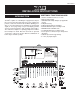
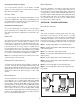
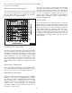
INS7162 RevTM INSTALLATION INSTRUCTIONS INTRODUCTION ADDITIONAL FUNCTIONS INCLUDE: The MP is capable of controlling the supply water temperature for up to nine ON / OFF stages based on outdoor temperature, control for the Domestic Hot Water (DHW) generation, a set point requirement or optionally an external input signal (0 - 10 V (dc)). A large easy to read display provides current system temperatures and operating status (FIG. 1).
This instruction manual is organized into four main sections: 1) Sequence of Operation, 2) Installation, 3) Control Settings, and 4) Testing and Troubleshooting. The Sequence of Operation section has seven sub-sections. We recommend reading Section A: General Operation of the Sequence of Operation, as this contains important information on the overall operation of the control. Followed by the sub-sections that apply to your installation.
DISPLAY Boiler Demand DHW / Setpoint Demand WWSD External Input Signal Offset FIG. 2 SYMBOL DESCRIPTION FIG.
Set Point DEFINITIONS When a set point demand signal from a set point system is present, the control operates the boiler(s) to maintain the supply water temperature at least as hot as the SETP setting. Refer to section F. The following defined terms and symbols are used throughout this manual to bring attention to the presence of hazards of various risk levels, or to bring attention to important information concerning the life of the product, see Figure 4 below.
ROTATION The control's Equal Run Time Rotation function is fixed at 48 hours. The firing order of the boilers change whenever one boiler accumulates 48 hours more running time than any other boiler. After each rotation, the boiler with the least running hours is the first to fire and the boiler with the most running hours is the last to fire. This function ensures that all the boilers being rotated receive equal amounts of use.
Resetting the Rotation Sequence BOILER MAXIMUM To reset the rotation sequence, set the Rotate / Off DIP switch to the Off setting for 5 seconds and then return the DIP switch to the Rotate setting. The boiler maximum is the highest temperature that the control is allowed to use as a boiler target temperature.
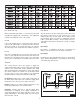
L O / HI OR FIRE DELAY L O / LO FIG. 9 The Fire Delay is the time delay that occurs between the time that the control closes a stage contact to fire a stage and the burner fires for that stage. The fire delays for the first and third stages in a boiler are adjustable using the F DLY 1 and F DLY 2 settings. The fire delay for the second and the fourth stages is fixed at 10 seconds, see Figure 10 below.
STAGE DELAY Fixed Differential The stage delay is the minimum time delay between the firing of stages. After this delay has expired the control can fire the next stage if it is required. This setting can be adjusted manually or set to an automatic setting. When the automatic setting is used, the control determines the best stage delay based on the operation of the system. If the user desires to have a fixed differential, this is set using the BOIL DIFF setting in the ADJUST menu (FIG. 11).
FIG. 12 FIG. 13 BOILER PUMP OPERATION In certain modes of operation, the control can operate the individual boiler pumps on each boiler in addition to the primary pump. The boiler pump turns on prior to the boiler firing and continues to run after the boiler is turned off. The amount of time that the boiler pump turns on prior to the boiler firing is determined by the BOIL MASS setting. If a BOIL MASS of Lo is selected, the boiler pump turns on 15 seconds prior to the boiler.
type of terminal unit. This improves the control of the air temperature in the building. BOILER INDOOR DESIGN TEMPERATURE The indoor design temperature is the room temperature that was used in the original heat loss calculations for the building. This setting establishes the beginning of the characterized heating curve, see Figure 15 below. ROOM The room is the desired room temperature for the building and provides a parallel shift of the heating curve.
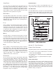
FIG. 16 HIGH MASS RADIANT (1) This type of a hydronic radiant floor is embedded in either a thick concrete or gypsumpour. This heating system has a large thermal mass and is slow acting (FIG. 17). LOW MASS RADIANT (2) This type of radiant heating system is either attached to the bottom of a wood sub-floor, suspended in the joist space, or sandwiched between the sub-floor and the surface. This type of radiant system has a relatively low thermal mass and responds faster than a high mass system (FIG. 17).
SECTION E: DOMESTIC HOT WATER OPERATION SECTION E1: DOMESTIC HOT WATER (DHW) DHW DEMAND A DHW Demand is required for the control to provide heat to the DHW system. A DHW aquastat or set point control is used as a switch in the DHW demand circuit. Once the control detects a DHW demand, the DHW Demand pointer turns on in the LCD and the control operates the boiler to provide a sufficient boiler supply water temperature to the DHW tank. The control operates the pumps as described below.
DHW MODE 4 - DHW IN PRIMARY / SECONDARY WITH PRIORITY When a DHW Demand is present, the Relay 9 / DHW contact (terminals 30 and 31) is closed and the primary pump contact is closed. Priority can only be obtained using external wiring. During a priority override, the Relay 9 / DHW contact is opened until the heating system has recovered before returning to DHW operation, see Figure 19. This mode can be used if a DHW tank is piped in direct return and a DHW valve is installed.
NUMBER OF BOILERS USED FOR DHW GENERATION The number of boilers used for DHW generation can be selected from one to the maximum number of boilers using the BOIL DHW setting. This applies when only a DHW Demand is present. If there are other demands present, the control does not limit the number of boilers operated. For correct operation, close attention must be paid to the mechanical layout of the system. When the control turns off the primary pump (Prim P1), flow to the heating system must stop.
operates set point and heating simultaneously by turning on the primary pump (Prim P1). BOILER TARGET DURING SET POINT The boiler target temperature during a set point demand is increased to at least the Set Point setting. This temperature is maintained as long as the control has a set point demand. SET POINT MODE SETP MODE 1 - Setpoint in Parallel Whenever a set point demand is present, the boiler(s) is operated to maintain the set point target.
INPUT SIGNAL EXTERNAL INPUT SIGNAL CONVERSION TABLES The control can accept either a 0 - 10 V (dc) signal or a 2 10 V (dc) signal. The External Input Signal setting must be set to the proper setting based on the signal that is being sent to the control. 0 - 10 V (dc) or 0 - 20 mA When the 0 - 10 V (dc) signal is selected, an input voltage of 1 V (dc) corresponds to a boiler target temperature of 50°F (10°C). An input voltage of 10 V (dc) corresponds to a boiler target temperature of 210°F (99°C).
INSTALLATION CAUTION Improper installation and operation of this control could result in damage to the equipment and possibly even personal injury. It is your responsibility to ensure that this control is safely installed according to all applicable codes and standards. This electronic control is not intended for uses as a primary limit control. Other controls that are intended and certified as safety limits must be placed into the control circuit. Do not open the control.
Set Point Demand OUTPUT CONNECTIONS To generate a setpoint demand, a voltage between 24 V (ac) and 230 V (ac) must be applied across the Setp / DHW and Com Dem terminals (8 and 7) (FIG. 26). The DHW MODE must be set to OFF. Primary Pump Contact (Prim P1) 9 10 Power The Prim P1 output terminal (11) is a powered output. When the relay in the control closes, 115 V (ac) is provided to the Prim P1 terminal (11) from the Power L terminal (10).
Boiler Return Sensor If a boiler return sensor is used, connect the two wires from the TST2311 sensor to the Com - and Boil Ret terminals (1 and 3) (FIG. 31). The boiler return sensor is used by the control to measure the boiler return water temperature. 1 2 3 4 Out Com Boil Boil + t – Sup Re 1 2 3 4 Boil Out Com Boil Ret + – Sup FIG. 30 1 2 3 4 Out Com Boil Botil + – Sup Re Relay 9 / DHW If a DHW pump or DHW valve is connected to the Relay 9 / DHW contact (30 and 31) (FIG.
A good quality electrical test meter, capable of reading from at least 0 - 300 V (ac) and at least 0 - 2,000,000 ohm, is essential to properly test the wiring and sensors. TEST THE SENSORS In order to test the sensors, the actual temperature at each sensor location must be measured. A good quality digital thermometer with a surface temperature probe is recommended for ease of use and accuracy (FIG. 33).
TEST THE OUTPUTS bleshooting information supplied with the boiler. (The boiler may have a flow switch that prevents firing until the primary pump (P1) or boiler pump is running.) If the boiler operates properly, disconnect the power and remove the jumper. Primary Pump (Prim P1) If a primary pump is connected to the Prim P1 terminal (11), make sure that power to the terminal block is off and install a jumper between the Power L and Prim P1 terminals (10 and 11) (FIG. 37).
CONNECTING THE CONTROL Make sure all power to the devices and terminal blocks is off, and remove any remaining jumpers from the terminals. Reconnect the terminal blocks to the control by carefully aligning them with their respective headers on the control, and then pushing the terminal blocks into the headers. The terminal blocks should snap firmly into place, see Figure 41. TM Install the supplied safety dividers between the unpowered sensor inputs and the powered or 115 V (ac) wiring chambers.
The Alarm / C.A. DIP switch selects whether a combustion air damper or alarm device is to be connected to the C.A. / Alarm terminals (12 and 13) (FIG. 45). ROTATE / OFF The Fixed Lead / Off DIP switch selects whether or not the first boiler is to be included in the rotation sequence. If the DIP switch is set to Fixed Lead, the first boiler is always the first to fire (FIG. 48). This DIP switch is only active when the Rotate / Off DIP switch is set to Rotate.
5 6 24
A 7 A 8 A 9 1 25
This item is only available if the External Input / Stand Alone DIP switch is set to Stand Alone. The item is only available if the External / Input Stand Alone DIP switch is set to Stand Alone. This item is only available if the External Input / Stand Alone DIP switch is set to Stand Alone.
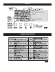
Boiler Minimum Boiler Maximum Fire Delay 1 Fire Delay 2 Combustion Air Damper Delay Boil Mass Stage Delay Boiler Differential Staging lohi DHW Mode 1 2 3 4 DHW Exchange Occupied DHW Exchange Unoccupied 27
(This item is only available when DHW MODE is set to OFF.) x m weather (This item is only available if the External Input/ Stand Alone DIP switch is set to Stand Alone.) time that the primary pump will continue to operate after the boiler demand has been removed.
TESTING THE CONTROL The control has a built-in test routine that is used to test the main control functions. The control continually monitors the sensors and displays an error message whenever a fault is found. See the following pages for a list of the control’s error messages and possible causes. When the Test button is pressed, the test light is turned on. The individual outputs and relays are tested in the following test sequence. present, the fourth stage is turned on.
ERROR MESSAGES FIG. 56 FIG. 53 The control was unable to read a piece of information stored in its memory (FIG. 53). Because of this, the control was required to reload the factory settings into all of the items in the ADJUST menu. The control will stop operation until all of the items in the ADJUST menu of the control have been checked by the user or installer. The control is no longer able to read the boiler supply sensor due to a short circuit (FIG. 56).
FIG. 59 Power Supply - 115 V (ac) + 10% 50/60 Hz 600 Va Relay Capacity - 230 V (ac) 5 A 1/3 hp pilot duty 230 VA Demands - 20 to 260 V (ac) 2 VA Sensors Included - NTC thermistor, 10 k (25°C + 0.2°C) B=3892 @ 77°F The control is no longer able to read the boiler return sensor due to an open circuit (FIG. 59). The control will continue to operate normally. Locate and repair the problem as described in INS7141.
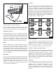
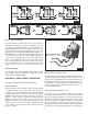
TYPICAL BOILER INSTALLATION 32
TYPICAL BOILER INSTALLATION (CONTINUED) 33
TYPICAL DWH PRIORITY HEATING PACKAGE SYSTEM MP2 Tekmar 150 Controller 34
NOTES 35
9/04 - Printed in U.S.A.