
User Manual

9004RX.01E
Contact Information:
Lodar Limited,
60 Sandwell Street,
Walsall. WS1 3EB. UK
Tel. +44 1922 613633
Fax. +44 1922 626991
www.lodar.com
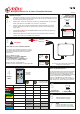
LED marked “POWER”
when lit indicates supply
to control circuits
is GOOD
LED’s marked
“F1 - F2 and M”
when lit indicate
an output
to that function
LED marked “S”
when lit Indicates
system is active
VOLTAGE
Working Range
12 Volts to 24 Volts DC
Nominal
LED marked “STATUS”
“Flash pause Flash etc.”
indicates coding window
is open.
LED stops flashing when
coding window closes.
LED lit continuously
when any Transmitter
button is pressed.
LED marked “FAULT”
Will flash an error code
when there is an active
fault.
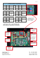
Jumper
Effect
Jumper
Effect
1
2
1
2
off
off
on
on
F1 Momentary
F2 Momentary
F2 Latch
F1 Latch
Jumper
Effect
Jumper
Effect
3
4
3
4
off
off
off
on
Parallel
Master
Continuous
Master
Jumper
Effect
Jumper
Effect
3
4
3
4
on
off
on
on
Master
=
F3 Momentary
Master
=
F3 Latch
11 Series Jumper Configuration
Position Position
Position Position
Position Position
NOTE: ONLY THE 11-102E SYSTEMS ARE
SUPPLIED WITH JUMPERS AS STANDARD
4 Function Transmitters
are supplied for use
with 3 Function systems
SPECIAL ORDER