3xLogic Inc Intelligent Video Surveillance Vigil Server Software v5.
Table of Contents 1 INTRODUCTION ................................................................................................................................................................ 5 2 SYSTEM REQUIREMENTS .................................................................................................................................................. 6 3 SOFTWARE FEATURES.........................................................................................................................
1.5.6 Live POS Data Window ............................................................................................................................................... 44 1.5.7 People Counting.......................................................................................................................................................... 45 1.6 CHAT ......................................................................................................................................................
6 LANGUAGE SWITCHER ................................................................................................................................................... 119 7 DVR SYSTEM DATABASE UTILITY .................................................................................................................................... 120 7.1 7.2 7.3 7.4 7.5 DRIVE MANAGEMENT TAB ................................................................................................................................
1 Introduction This guide describes the installation and operation of 3xLogic’s Vigil Server Software (Vigil Server). This version of the User’s Guide is current to Version 5.00 of Vigil Server. Vigil Server is a powerful, yet easy-to-use, software package for viewing and saving video footage. 3xLogic (www.3xlogic.com) produces enterprise class DVRs and state-of-the-art surveillance software.
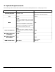
2 System Requirements The following table outlines the minimum and recommended platforms for running Vigil Server. PC Feature Operating System CPU Minimum Recommended Windows 2000 Windows 2000 SP4 Windows XP Professional SP2 2.0GHz 3.0GHz 512MB A minimum of 768MB of RAM is recommended for 32 camera systems, or systems with audio recording. RAM A minimum of 1GB of RAM is recommended for 8 or more hi-definition IP camera systems 1GB A minimum of 1.
3 Software Features This section describes some of the features of Vigil Server. Feature Details Individual Camera Settings Configure each camera independently: brightness, contrast, sharpness, hue, resolutions, and more. Configurable CODEC Settings Change CODEC settings for each camera such as compression, quality, noise reduction, and more. IP Camera Support Vigil Server supports up to 32 IP hi-resolution cameras without the need for an installed capture card.
4 Installation 4.1 Windows Installation Notices Warning: During the installation you may get a Windows File Protection and/or a Windows Logo testing notice. Please follow the following instructions when this happens. Failure to do so can result in a non-functioning software installation.
Click “Yes” 4.2 Installation If you downloaded your install kit for Vigil Server, navigate to where you saved the file using Windows Explorer and double-click the EXE file that you downloaded to begin installing. Note: To update an existing version of Vigil Client, use the Vigil Client update (VGL) file instead of the Vigil Client install package (EXE). If you are installing from CD, load it in your CD-ROM drive and run the EXE on it.
Ready to Install Summarizes installation settings and gives you one more chance to abort the installation. Installation The actual install process. Copies necessary files, creates shortcuts, installs registry information, media drivers and CODECS, database and scripts, and any other optional software. Adobe® Acrobat (used for viewing the PDF User’s Guide) and Remote Administrator (used to remotely administrate your computer) have their own install processes.
b. Select the data terminal type from the dropdown list and select its configuration information. c. Select the “COM Ports” tab to specify COM port settings for the data terminals.
1 Operation This section details the general usage of Vigil Server software. This is the normal view that will appear after the program has finished loading. Notice that the program will automatically load at Windows start-up, automatically log on, and open the “Live Viewer” window. These options can be changed if desired. 1.1 Main Toolbar This table is a quick listing of the main toolbar buttons and their usage. corresponding window in later sections.
Opens the “Live Audio Settings” window. button opens the context menu which can open the “Audio Recorder Clicking the Controls” window. Opens the “Live Viewer” window. If “Hardware Rendering” has been enabled and is supported by your capture card, you can click the button. This opens a context menu allowing selection of either “Software Rendered Cams” or “Real Time Cams”. Opens the “Search” window. button opens the context menu which allows you to open the “Custom Clicking the Search” window.
1.2 Live Viewer Window By default, the “Live Viewer” window will open once the program has loaded. If “Auto Logon” is disabled, you must log in before the “Live Viewer” window is opened. Note: The Live Viewer window may be slightly different depending on the capture card that is installed, the rendering mode enabled (hardware vs. software), and the number of supported video channels. See section 5.2.6 for details. The “Live Viewer” window can be in either software rendered mode or hardware rendered mode.
1.2.1 Changing Live Viewer Camera Layout Use the buttons in the top section of the “Live Viewer” side toolbar to select the viewing style. If you have more cameras enabled than can be displayed by the current view settings, you can right click on the layout icon and select a page of cameras to display.
1.2.2 TV Output Switch Vigil Server can display two video feeds to analog monitors. With the XECAP series video capture cards, one of these feeds can be configured as a multiplexed video output similar to the “Live Viewer”. Click to change the camera displayed on the monitor by selecting the camera number. On capture boards supporting Mux/Analog Out, you can also select the “Setup Analog Out Multiplexer” menu item, which opens the “Analog Out Multiplexer” window.
1.2.3 Restore Original Display Layout Undoes any layout changes that have been made since the “Live Viewer” window was last opened. To reload default Window sizes and locations for all screens, select “Tools” | “Reset Screen Layouts to Default” from the menu, or select “Reset” from the Tools button dropdown. 1.2.4 Enabling/Disabling Captions Toggles captions on the “Live Viewer” video feeds. Note: Captions are not included in the recorded footage. 1.2.
1.2.7 Camera Quick Access To quickly select a camera for single view display mode, click its corresponding number. It also provides a simple way to check which cameras are recording. Green: “Constant” recording mode and is recording Blue: “Motion” recording mode and is recording (motion detected) Red: “Motion Alarm” recording mode and is recording (motion detected). If POS data alarms are configured, it can also mean a POS data alarm.
1.2.9 Media Drive Information The “Media Drive Information” section is a live view of the status of the video and audio data storage drives that are configured on the DVR. The status of the data drive is indicated by its icon: : Configured drive : Currently recording on this drive : Drive error; contact your system administrator : Currently recording to an alternate recording device; contact your system administrator The percentage free space is indicated following the name of a drive.
Dropdown selection box Changes the selected PTZ camera. Shows/hides the extra PTZ camera controls. Controls Use the mouse to click and drag the blue dot in the middle of the Pan-Tilt control in the desired direction. The speed at which the camera moves increases as the dot is dragged closer to the edge of the circle. The alternate directional controls are displayed when the selected PTZ camera doesn’t support a full range of motion (i.e.
To move the camera to an existing preset, select a preset from the dropdown list and click “Goto”, or click the button with the preset number on it. Patterns Controls the saved pattern of movement of the selected camera. Camera patterns are stored within the camera. Select a pattern from the dropdown selection box (this will overwrite the existing saved pattern) and click “Record”. Use the other control buttons to move the camera in the desired pattern.
Camera menu navigation buttons. Camera menu select button 1.3 Searching and Playing Back Recorded Video Vigil Server offers a robust set of tools for searching and rapidly identifying video footage and Point of Sale (POS) data of interest. To open the search screen, either click “Search” on the main window toolbar or select “Search | Search Footage and Data” from the menu.
From / To You can specify the starting date/time and end date/time of your search. By default, Vigil Server limits your search to be within a single day. This can be changed in the software settings. Presets This drop down includes preset search intervals in hourly increments from 1 hour up to 8 hours. Additionally, selections for 15 and 30 minutes can be added by checking “Quick Retrieve Short Intervals” the “Search” settings. When a selection is made, the From/To times are adjusted appropriately.
Or / And Logical operators that will assist in searching with multiple criteria. By default, this is the OR operator, which will match any results, in any of the POS data criteria fields. The AND operator will only match results that have the same POS data criteria, in all the used fields. Value Matches results in the Code column. By default, any price is selected. If you wish to match a certain value, select an operator and input a value. The “>=” means “more than or equal to” the value that you input.
1.3.3 Video Search Results After completing a search, the video results are displayed in the Video Search Results pane. This pane is also expandable/collapsible. This button allows you to change between the visual search and a simpler tabular search. Allows you to zoom in and out in the Video Search Results pane to allow you to select footage with greater precision. Changes the playback window from a single screen layout to a 2 x 2 layout.
The tabular search simply shows a table with the start and end dates of the available video footage. cannot display gaps in video footage. 1.3.4 It Creating and Running a Custom Search If you find yourself making the same search regularly, a “Custom Search” can be saved. The “Custom Search” window can be accessed from the “Quick Retrieve” dropdown. It can also be opened from the menu (“Search | Custom Search”). When selected, the “Custom Search” window will appear.
Description The name for your search that will appear in the “Custom Search” list. Time Filter The start time and end time to be searched. Cameras Data Select the cameras to search, or select “All Cameras” The custom search will include the POS data criteria specified. Once you’ve completed inputting the search information you would like to save, click “OK”. The window will close and bring you back to the “Custom Search” window.
1.3.5 Video Playback Once footage has been selected for playback it will be loaded in the playback portion of the “Search” window. Footage information is displayed below the playback window. This information includes the playback status, the date and time of the footage, the nominal frame rate if currently playing, the resolution and recording codec of the footage, the current frame of the footage, and if the zoom feature has been used then [Sub range] will be displayed.
A number of controls have been provided to make navigation and advanced features more accessible: Click and drag the variable speed playback slider to change how fast the footage is played back. Playback up to every fifth second of footage. The “Variable Speed” playback tool tip displays the number of times faster the variable speed playback is than the “Fast Backward” or “Fast Forward” buttons.
1.3.6 Synchronized Multi-Screen Playback Select Multi-Screen to playback up to four cameras simultaneously. The playback window will be divided into quadrants. Quadrants are filled in clockwise order beginning in the top left. To add a camera to the playback, click on its name or some point within its timeline. If all quadrants have cameras loaded, clicking a new camera will replace one of the initial cameras. Footage will play back from all loaded cameras simultaneously.
1.3.7 Using the Smart Search Smart searching allows you to further refine your video search by performing a custom motion detection search within a specified region of the loaded footage. To perform a smart search, first select the “Smart Search” tab from the “Advanced Features” bar. To define the motion search region, simply click and draw within the playback window. A mask pattern will be overlaid on the playback window. Any time you click on a clear area, you are expanding the mask.
1.3.8 Zooming During Playback You can zoom in on any footage being played back by selecting the “Zoom” tab from the “Advanced Features” section. When the cursor is moved over the playback window, a zoom outline will be displayed to indicate the region that will be magnified. Left clicking zooms in and right-clicking zooms out of the image. The magnification factor is displayed in the upper right-hand corner of the playback window.
Note: You can only adjust a paused image; adjustment of footage during playback is too CPU intensive. Any adjustment you have made will be reapplied when footage is paused again. 1.3.10 Using Markers to Create a Sub-Range During playback, if only a sub-section of the loaded footage is of interest, it can quickly be selected by using “Markers”. To use markers, select the “Markers” tab from the “Advanced Features” section.
Select the desired audio channel to playback from the “Channel” dropdown. All Audio Video Only Audio Plays back recorded audio from the selected channel, regardless of whether there is recorded video at the same time. Plays back recorded audio from the selected channel, only when there is corresponding recorded video at the same time. Note: The “All Audio” option is not available when using visual search. To enable this option, disable “Visual Search” from the search options.
If “Real-Time Authentication” (in “DVR Settings | Search tab”) is enabled, during playback if a frame is does not pass authentication a large red X is displayed over the frame. 1.3.14 Printing, Saving, or Copying POS Data To print data to the default printer, right click on the data records and select “’Print”. You can also select the printer button and select “Print Data” from the context menu. To save data to a preset destination, right click on the data records and select “Export”.
Opens the OSD menu, allowing you to select open the “Configure OSD” window Dwell Time Number of Lines Background Transparent/Color Font Color/Size/Bold Horizontal/Vertical Offset Column Selection The number of seconds a data record will remain on-screen. The maximum number of records to display at a time. Change the text background color/transparency. Change the font color/size/boldness. The number of characters to offset the text from the left/top side. Specify which columns you wish to have displayed.
1.4.1 Exporting Images Single frame shots can be saved in either Bitmap (BMP) or JPEG (JPG) format. BMP images retain all of the original image detail, but are typically much larger than JPG images as a result. JPG images are compressed but typically are indistinguishable from the original image with a quality of 70 or greater. Click to open the Export sub-menu. Select which type of media you wish to export. BMP Saves the still image as a BMP image. Select the export destinations and enter a filename.
Saves the current video footage as an AVI video. Select the export destinations and enter a filename. Clicking the “Advanced” button will open the “CODEC Settings” window that allows you to select and configure the CODEC used during the encoding process. AVI Click “Save” when finished or “Cancel” to exit without saving. MJPG Saves the current video footage as a MJPEG. Select the export destinations and enter a filename. Click “Save” when finished or “Cancel” to exit without saving.
If you are exporting from multi-screen playback, when choosing to export video, you will have the option of exporting the “Selected Camera” or “All Cameras”. Choosing “Selected Camera” will export only the currently selected camera footage. Choosing “All Cameras” will export footage from all currently displayed cameras to separate files. The files will have the camera name appended to the filename you enter. 1.4.
V-POS Update… Automatic Updates Register DVR 1.5.1 If the V-POS software program is installed, this option simply provides a quick way to load the application. It is especially useful if Vigil is configured for Kiosk mode and the normal Start menu is disabled. Opens the Local Update Utility that provides a small program to perform software updates for DVR applications. Opens the Update Service window. More information about this utility can be found later in this manual.
This program is for advanced users as a lot of the returned information may be cryptic or confusing for some. Essentially the program allows you to search the logs by using a variety of criteria such as date/time, error codes, IP address, or for a particular module. 1.5.3 Alarms Window The alarms tool provides a listing of alarm events and allows quick playback of alarm footage. To open the alarm tool, select “Alarms” from the tools drop-down of the main window toolbar.
Alarms are listed in a tabular form with the camera number, camera name, type of alarm, and date and time of the alarm. New alarms that have not yet been acknowledged are shown in red. Acknowledged alarms are displayed in yellow. Acknowledges the selected alarm and changes its highlighted color to yellow. Acknowledges all visible alarms and changes their highlighted color to yellow. Clears selected alarm from the “Alarms” window. Clears all alarms from the “Alarms” window.
The table includes information of the client’s remote host name or IP address, the remote host connection port, the locally connected port, and the last activity time of the connection. The update frequency of the table can be adjusted by selecting a number of seconds from the “Update Frequency” drop-down box. 1.5.5 File Exports Browser The export file browser provides a thumbnail file browser for exported footage and still shots. File navigation is similar to Windows explorer.
Open a File Double-click the desired file in either the “File Browser” or “Thumbnail Browser” screens. This will open the file using the standard Windows assigned program. Delete a File Right-click the desired file, in either the “File Browser” or the “Thumbnail Browser” screens, and select “Delete”. You can also select the file and use the menu by going to “File | Delete File” as well as selecting the file and pressing the Delete key.
1.5.6.1 Filter Live POS Data To filter POS data by register number, right-click on the “Live Data” window and select “Data Filter” Enter the register number, or leave it blank to view POS data from all data terminals, and click “OK”. 1.5.6.2 Saving Live POS Data POS data can be saved in one of three ways: exported to a text file, printed, or copied to the Windows clipboard. Copy data Right-click the desired POS record and select “Copy Line”.
The “People Counting” window presents in and out hourly summaries for all cameras configured for “People Counting”. The columns include: • Camera – The camera number and name. • From – The start of the counting interval. • To – The end of the counting interval. • In – The number of entrances during the interval. • Out – The number of exits during the interval. Search Right-click the desired counting log and select “Search”. This will open the “Search” window for the selected camera and time period.
“Talk” button to manually start and stop sending voice data. When “Hands Free” is unchecked, click “Talk” to send voice data. Unclick “Talk” to stop sending voice data. Talk Voice Detection Graphs The voice detection graphs provide a visualization of voice data detected in chat session. Send Text Type text into the textbox and then click “Send Text”. Sensitivity Use the button to expand the controls section. Use the slide bar to adjust the chat audio sensitivity. 1.
Stops recording audio on the selected channel. Drive Information The drive information section is a live view of the status of the configured audio storage drives: - Configured drive - Currently recording on this drive - Drive error, contact your system administrator 1.7.1 Live Audio Settings The “Live Audio Settings” window is used to adjust recording levels and monitor live audio. Opens the “Live Audio Settings” window. You can also “Audio | Live Audio Settings” from the menu.
1.8 Video Recorder Controls The “Recorder Controls” screen allows you to control which cameras are recording footage and provides a quick summary of the camera configuration. To open the Recorder Controls screen, click the “Recorder” button on the main window toolbar. Opens the “Recorder Controls” window. You can also “Tools | Recorder” from the menu. The icon to left of each camera indicates that camera’s recording status: Camera is currently recording. Camera is currently stopped. Camera is disabled.
2 Settings Vigil Server is a complex software application that interfaces with a wide variety of hardware configurations. Every effort has been made to present a comprehensive set of customization controls to configure your DVR to match your needs. The following chapter will describe in detail all of the settings available. Feel free to skip those sections that don’t apply to your configuration. Opens the “DVR Settings” window. You can also “Tools | Settings” from the menu.
2.1 Camera Setup Tab The “Camera Setup” tab provides all of the settings for configuring DVR-controlled cameras. The settings are divided into two sections: general camera setup and a series of tabs controlling recording options. 2.1.1 Camera Settings and Setup The camera setup settings allow configuration of the camera image, resolution, recording speed, buffering, and recording codec. Network cameras are also enabled here.
Resolution Select the desired recording resolution from the drop-down list. Recording Enable or disable recording of the selected camera. Pre Buffer The number of seconds of footage to be recorded prior to a motion detection or alarm event. Opens the “Recording Speed” window. You can set a different recording speed for each recording type: Constant, Motion, and Alarm. Use the dropdown list to select the desired number of frames per second. Returns the settings of the selected camera to default values.
2.1.2 CODEC Settings The CODEC Settings allow advanced configuration of the recording codec used for storing video footage. Opens the “CODEC Settings” window. Two video encoding CODECS are currently available for recording video footage: AZTECH and MPEG4 CODECS. Depending on your DVR model, it may use H264 recording. This cannot be changed to another codec and has slightly different customization options.
Resets CODEC settings to their default values for the selected camera. Picture Quality Noise Reduction 2.1.2.1 Adjusts picture quality of the recorded images. Higher quality video will occupy more space on disk. You can use the slider or the text box to change the values. Adjustment used to reduce video noise on grainy video. AZTECH CODEC Settings The AZTECH CODEC is the default codec used for recording video footage. To change to the AZTECH CODEC, select “AZTECH” from the CODEC drop-down box.
Use B Frame Uses bi-directional frames to decrease the file size of recorded footage Caution: This is a CPU intensive setting. 2.1.2.2 MPEG4 CODEC Settings To switch the recording CODEC to MPEG4, select the “MPEG4” option from the CODEC drop-down box. Keyframe Rates Motion Search Scope Sets the number of keyframes recorded per second. The higher the value, the greater the data space needed for recording, but the higher the quality of the video. Changes the size of the regions used to detect motion.
2.1.3 Advanced Settings In the “Advanced Settings” window, the cameras are grouped into “Bank” tabs that represent the physical camera banks in the DVR. This allows the user to maximize the capture resolution and recording speeds for each camera bank. When the number of FPS is changed in the “Advanced Settings” window, it is applied to all recording modes. Camera Dropdown Select a camera number within the selected bank tab.
Type The type of storage location. Local Drive. Path The path where the image files will be uploaded (can only use pre-existing directories). Local Directory: “C:\images” Network Directory: “\\ComputerName\SharedFolder” FTP site: “ftp://ftpserver/folder” FTP User Name and Password Options are FTP Location, Windows Network Share, and Enter the user name and password, if required, for the path. FTP Timeout The time to wait in seconds before a timeout occurs.
Vigil Server currently supports several types of network cameras, including HTTP cameras, Acti, IQeye, Panasonic, Sanyo, other Vigil Server DVRs, and more. Type The type of network camera. See section 15 Supported Network Cameras for a complete list of all supported network cameras and recommended settings configurations. Address The camera address of the IP camera, or if this is an HTTP camera, the HTTP address of the camera (do not include “http://” at the beginning of the address).
Live Resolution User / Password Recompress This is the resolution of the image that will be displayed on the Live Viewer. If you are connecting to a 3MP IP camera, the resolution is much higher than your monitor is capable of displaying, so it makes sense to reduce the resolution to minimize CPU usage. The user name and password to connect to the camera. automatically entered. The default values are This will recompress the image using our AZTECH codec and resize the image to 352x240 before saving.
Address: IP Address of the Vigil Server DVR Port: Live Video Port, default 22802 Camera Number: The camera input number on the remote DVR to be used Timeout: Number in seconds before connection time Decoding FPS: The Decoding FPS should be set to a value equal to or greater than the recording key-frame rate on the remote DVR camera input. Use the All Frame setting for camera inputs with low key-frame recording (i.e.
Here you configure which regions of the video image are to be used for motion detection. To do this, simply draw on the video window. A semi-transparent overlay will be drawn over top of the video. This marks the motion detection region. To clear motion detection regions, click and draw on them and they will be removed. Invert Clear Swaps masked and clear regions. Clears all masked areas. Set All Test Motion Masks the entire image for motion detection.
Trigger Blocks Motion Sensitivity 2.1.6.2 Determines how many blocks of the image must change to count as motion. Adjust the “Motion Sensitivity” slider to control the amount of motion required to trigger recording. Use a very sensitive setting to detect almost all motion, or a less sensitive setting to require only very large movements to trigger recording. Scheduled Recording If you selected Schedule from the “Recording Mode” drop-down list, the “Schedule” window will appear.
Expands and contracts the time graph horizontally. setting your time periods. This allows for better precision in Expands and contracts the time graph date graph vertically. Note: The smallest time interval that can be used is 15 minute periods. Moving a time period Click and hold the “Shift” key and click-and-drag the section. Copying a time period Click and hold the “Ctrl” key and click and drag the section.
Camera Control Type The type of PTZ camera that is connected to your DVR. COM Port The COM port that the PTZ camera is connected to your DVR. If a message titled “CONFLICT” appears below the camera type drop-down, then there is another camera or data terminal that is set up to use that COM port or the address specified. The name of the conflicting camera or data terminal is displayed at the end of the message.
Allows you to set up a pattern, preset, or tour after an alarm input has been triggered. Can be used to turn a PTZ camera to a specific doorway for example. You must first assign the input to the specific PTZ camera in the “Alarms/Relays” tab in the “Settings” window. Input dropdown Mode Name/Number Auto Restart PTZ After Alarm Dwell Time Select which digital input to use as the trigger event. Selects which action to apply after the alarm event has been triggered.
2.1.8 Motion Alarm Tab Motion Alarms allow you to configure powerful motion detection alerts that include full control over motion quantity, size, area, speed, and direction of motion. In addition to the alarm itself, a wide variety of alarm notification settings are available. To configure Motion Alarms, select the “Motion Alarm” tab from the camera settings screen. Motion Alarms can be used in addition to any other recording mode.
2.1.8.1 Motion Alarm Settings The “Motion Alarm Settings” window is an advanced version of the already discussed “Motion Settings” window. In addition to standard motion detection, the motion alarms add direction and speed sensitivity. This is accomplished by defining a motion vector with a timeout setting. A motion vector is composed of two or more motion detection regions and one vector. A motion vector represents an object moving through specific areas of the image in a specific direction.
Note: If there is no motion vector arrow specified, any of the selected regions will trigger a motion alarm. Motion vector regions with motion detected are identified with a red square. If the camera is set to record “Motion Alarm Only”, then the camera will not record individual motion vector regions that are detected, or multiple regions that are detected but not in the correct order. If the camera is set to record “Motion”, it will record using the motion settings set up in the “Recording Mode” tab.
2.1.8.2.1 General Tab Schedule Enabled Check the “Enabled” box to record a schedule in which the motion alarm can only be triggered. Click the “…” button to open the “Schedule” window or edit an existing motion alarm schedule. Output Relay Output Relay When an output relay is selected, the relay is triggered when the motion alarm criteria is met. Trigger There are two trigger types: a momentary trigger of 2 seconds or a latched trigger which will stay triggered until motion stops.
To add a time period where the motion alarm is enabled, click and drag across the desired time slot. Areas that are blank (no color) will disable the motion alarm event for those time periods. Note: Blank areas will not trigger a motion alarm, however, depending on the recording mode, they will still record footage. This schedule only affects the motion alarm itself. Motion Alarm Enabled Sections that have motion alarm enabled are colored green. Expands and contracts the time graph horizontally.
Viewing the start and end times of a section Deleting a time period Deleting a schedule Apply Schedule To All Cameras 2.1.8.2.2 Select the section by clicking on it. The start and end time of the selected section are displayed near the bottom left corner of the “Schedule” window. You can also mouse over the any part of the section and the time will be displayed near the bottom as well. Select the section by clicking on it and then click “Delete”.
Audio Notification Settings Enable Enables audio notification when a motion alarm is triggered. Two audio notification types are available: • System Beep - Plays a system beep • Wave File – Click the “…” button to select a WAV file that will be played. Auto Acknowledge Enable Enables to automatically acknowledge motion alarm notifications after the specified number of seconds.
From (Address) Subject Email Body Attach Still Shot The email address of the entity that will be sending the emails. This text will be the subject line of the emails. This text will be included in the body of the emails. Allows a still image from that camera to be attached to the outgoing email. image is from the beginning of the motion alarm event. Recipients These are the lists of recipients who will receive motion alarm notifications.
Remote Client Notification Settings Enabled Push Still Shot Settings… Enables remote client notification. When configured, a still shot from the selected cameras will be uploaded to the locations specified when a motion alarm is detected. Please see section 6.1.4 Push Still Shot to Server for more information. Client Connections A list of remote computers running Vigil Client Allows you to add another remote client to the notification list. feature, the dialup connection must be created in Windows.
Notify All / First Allows you to select if all client connections receive motion alarm notifications or only the client connection at the top of the list. Connection Attempts The number of attempts to retry sending a motion alarm to a client connection. Retry Delay Number of seconds to wait between retries. 2.1.9 Video Loss Tab If the video signal is lost from an enabled camera, you can specify an action to take in the “Video Loss” tab.
Click the “Email Settings” button to open the Email Settings screen. In the Email Settings section, enter the details for the email that will be sent. Email Header Options From (Name) From (Address) Subject Email Body The name of the entity that will be sending the emails. The email address of the entity that will be sending the emails. This text will be the subject line of the emails. This text will be included in the body of the emails.
Delete Note: Prompts to remove the selected email address from the recipients list. For email to function properly, a valid SMTP Server must be configured in the “DVR Settings” tab. 2.1.10 Live Overlay Tab For live overlay DVR systems, live overlay camera settings are available. appearance of the live overlay image. These settings modify the Live Overlay Brightness Contrast Increases/decreases the brightness of the image recorded. Increases/decreases the contrast of the image recorded.
Moving bodies are outlined by a dashed box on the preview display. An entrance or exit is defined when the centre of the boxes cross from one side of the boundary line to the other. In/out counters are attached to each detected person and total count is displayed at the bottom of the preview window.
Boundary Orientation These settings define the location of the boundary line. The boundary line is displayed on the live image as a dashed line. If the centre point of a moving entity crosses this boundary line, it will be counted as an in/out depending on the direction of the crossing. Reverse Count Direction Changes the way in/outs are counted by reversing the direction across the boundary line.
Site Name The name of the DVR Site where the Vigil Server is located. The site name is included when saving still images and is also displayed in DVR Health Monitor. Offsite Backup on Alarm Enable Offsite Backup Enables footage to be automatically exported to the specified offsite location when an alarm occurs. Click “…” to browse to a network location where the footage will be saved.
The central SQL database feature is designed for DVRs with extended storage, which can cause the DVRs SQL database to exceed the 2GB limitation of the MSDE version of SQL which is used in Vigil Server. Warning: Qualified technicians only should modify Central SQL Database settings. Incorrect use of this utility can cause system failure. If the DVR is experiencing database issues, please contact your system administrator or 3xLogic technical support.
2.2.1 General Tab Auto-Start Recorder Enables the DVR to start recording footage as soon as the Vigil Server program is launched. If not enabled, the user must manually start the recorder using the “Recording Controls”. Enable Logging Enables Vigil Server log files. Redundant DVR A redundant DVR is used for backup recording in case of DVR failure. If “Redundant DVR” is enabled, the Sentinel service will not display an error if there is no footage recorded in 24 hours.
When enabled, the Vigil Screen Saver is displayed after the specified number of minutes of inactivity on the system. Screen Saver Note: The Vigil Server system will continue to record while the screensaver is displayed. When this feature is enabled and an error is recorded in the Audit Log, the “Error Alert” window is displayed until the error has been acknowledged.
Presets – Select a preset from the dropdown list to change all of the ports to that preset. Change a Port – Type in a port number directly into the text box to set a custom port number. Disable a Port – Uncheck the box beside the port. If a port is disabled, Vigil Clients connecting to the server will be unable to use the feature corresponding to that port. Reset to Defaults – Click to reset the ports to their default settings. Reset Initial Footage Date 2.2.
Auto Logon When this is enabled, a dialog box prompts for a username and password. The username and password entered will be used to log into Vigil Server automatically when the program is launched. If this is disabled, Vigil Server will prompt for a login every time it starts. Scheduled Reboot When enabled, the DVR will reboot automatically after the specified time lapse occurred and during the day and time indicated. 2.2.3 Live Tab The “Live” tab controls features of the Live Viewer.
2.2.4 Search Tab The “Search” tab includes parameters for modifying the search behaviour of Vigil Server. Limit Search To One Day When enabled, the “Search” window will be limited to performing searches a single day at a time. To enable multi-day searches, uncheck this box. Quick Retrieve Short Intervals When enabled, the “Quick Retrieve” dropdown list in the “Search” window displays short intervals of 15 and 30 minutes as well as the regular selection.
2.2.6 Clients Tab The “Clients” tab indicates how Vigil Client connections should be handled. Resolve Client Name When enabled, the IP addresses of clients who log in remotely to the Vigil Server are queried to find the computer name of the remote client. Max Network Connections Sets the maximum number of remote connections allowed to access Vigil Server at the same time. Note: Each Live Viewer window, playback window, and settings screen takes up one or two “connections” to the Server.
2.2.8 Hardware Tab The “Hardware” tab informs Vigil Server of the specific hardware you may have installed as well as configures the automated time synchronization. This setting restricts the amount of data the video capture card is allowed to push through the PCI bus. The default setting is 20 or 22.5 MB/s, depending upon the capture card. Setting this too high will result in poor performance of the DVR. Max Allowed PCI Bandwidth Warning: If this setting is changed, undesired side effects may result.
Note: The NTP test will not record an event in the Windows Event Log if the time is already correct. 2.2.8.1 Configuring AUX Devices Adds a new AUX device to the list. Type – The particular type of DIO device you are adding: ACTi Encoder Add Specifies you are attaching an ACTi encoder device. information. Input the connection Comart DIO Specifies an onboard DIO board (optional on certain capture boards). which configuration and DIO model number.
Comart USB 1616-A Specifies a USB attached DIO board. Enabling System Beep causes the speaker located on the USB DIO to chirp on events such as triggered relays and opened/closed alarm inputs. ADAM 4052 / 4068 Adds an ADAM 4068/4052H COM port attached DIO device. settings here. Specify COM port ADAM 6060 Adds an ADAM 6060 network attached DIO device. Specify TCP/IP settings here. Edit Delete Allows for changes to the configuration of the selected DIO device. Uses similar windows as the Add function.
2.2.9 Proxy Tab The “Proxy” tab allows you to configure a connection to a proxy server if it is required on your network to reach IP cameras. 2.2.10 Help Menu Tab The “Help Menu” tab allows the user to configure an application that can be run from the Help Menu. Enable Custom Help Action Menu Text Enables the customized help menu item. The directory path to the executable program. file. Click “…” to browse directly to the This is the text that will appear in the Help menu of Vigil Server.
2.3 Media Drives Tab The “Media Drives” tab configures the entire video recording and export destinations for the DVR. There are three types of Media Drives: Video Storage Drives, Alternate Video Storage Drives, and Export Destinations. • • • Video Storage Drives – Video Storage Drives are the main drives where video footage is stored. If all of the Video Storage Drives are offline, the Alternate Video Storage Drives will be used until the Video Storage Drives return online.
Note: Deleting a location does not remove the physical destination, only the reference to it within Vigil Server. Note: If a Video or Alternate Storage Drive is deleted, the user will be prompted whether they also wish to delete any database records of the footage at that location, and whether they wish to delete any saved footage at that location. 2.3.1 Video Storage Drives When a video storage drive is added or edited, the “Media Control” window is displayed.
2.3.1.1 Data Partitioning for Video and POS Alarm Video Footage Data partitioning has been added to Vigil Server allowing for better user input as to how data is saved to the hard drive. Data partitioning allows you to set up logical divisions between both standard alarm and POS alarm video files and normally recorded video. This allows the video scavenging process to skip alarm video files and allows you to save these types of video footage for longer periods of time.
Destination Path 2.3.3 Select the hard drive partition you want to use to record video data to. Export Destinations When an export destination is added or edited, the “Media Control” window is displayed. Video Still/Motion Export Destinations are used to store exported video footage. You must set up destinations before saving video footage or still images. Destination Name A name for the destination to appear in Vigil Server.
2.5 User and Group Management Tab The “Users” tab allows the configuration of users on the DVR with specific permissions. Each user belongs to a group and each group has a set of permissions. 2.5.1 Add/Modify a User To add/modify a user, select the Users button. Click the “Add” button and enter a username, password, and group in the “Add New User” window. Add a User Select the user from the dropdown list and click the “Edit” button. password or change the group in the “Edit Selected User” window.
Note: A user can only belong to one group. Delete a User 2.5.2 Select the user from the dropdown list and click “Delete”. Add/Modify a Group To add/modify a group, select the Groups button. Click the “Add” button and enter a group name in the “Add New Group” window. Once the window closes, you can place checkmarks on the desired privileges for this new group.
2.6 Relays/Alarms Tab The “Relays/Alarms” tab configures the input alarms and associated notifications settings for the DVR. 2.6.1 Digital Inputs Digital inputs are alarms triggered by external circuits. The input alarm can be used to trigger audio and video recording. To configure a digital input, select the “Input Number” from the dropdown list and check the “Input Enabled” box.
2.6.1.1 Settings Tab Dwell Timer The number of seconds the digital input/output remains active after a trigger occurs. Normal Open/Closed If the digital input/output is normally open, select the “Normal Open” option. If the digital input/output is normally closed, select the “Normal Closed” option. When the input changes state, the alarm will be triggered. Auto Acknowledge Mark enabled for the alarm to be automatically acknowledged after the selected number of seconds have passed.
another alarm input Note: Importing the schedule of another digital input will overwrite the schedule of the current digital input. Viewing the start and end times of a section Deleting a time period Deleting a schedule Select the section by clicking on it. The start and end time of the selected section are displayed near the bottom left corner of the “Schedule” window. You can also mouse over the any part of the section and the time will be displayed near the bottom as well.
2.6.1.2 Client Connections Tab The “Client Connections” tab controls input alarm notification to Vigil Clients. Click “Add” to open the “IP Address” window. Type in the IP address of the remote client or mark the “Use Dialup” box if you wish to use a Windows dialup connection. Add a Client Edit a Client Delete a Client Up/Down Arrows Select a remote client and click “Edit” to change that remote clients IP address. Select a remote client and click “Delete” to remove it.
2.6.1.3 Notification Settings Tab Email Notification Test Email When enabled, an email is sent when an alarm is triggered. Click “Email Settings…” to change to the format and recipients of the notification email. Sends a test email based on your notification settings and email configuration.
Enter the appropriate details for the email that will be sent. To add, edit, or remove email recipients, use the “Recipients” section and the appropriate buttons. Enabling “Attach Still Shot” will add a still image of the selected cameras to the outgoing email. This image is from the beginning of the triggered alarm event. Note: For email options to function properly, a valid SMTP server must be set up correctly in the “DVR Settings” tab. Popup Alarm Screen When enabled, opens an alarm window on the DVR.
COM Port Register Number The DVR COM port to which the terminal is connected. Ensure that the COM port settings match those of the terminal. The POS register number. POS Alarm Settings Enabled Dwell Time Output Relay Trigger Enables a certain text trigger to fire an alarm event which will be recorded as POS alarm footage (if data partitions have been enabled), as well as fire an output relay if desired. The time in seconds that the POS alarm event will last for.
Filter Method You can select to apply an AND/OR operator to the filter values. This operator will apply to all fields in POS Alarm Filters. Note: For the POS alert to function, the text must be an exact match to the POS data record including spaces, but it is not case-sensitive. 2.7.1 General Settings Tab The “General Settings” tab controls the display and storage of POS data.
Enable POS Data Email Notification When enabled, an email will be sent to specific recipients with POS data information. Data records recorded since the last check and that match the criteria in the “Filter Settings” are emailed. Email Frequency Specifies the time between emails that will be sent. Filter Settings… In the “Data Email Notification Filters” window you can specify which conditions to filter for when sending POS data emails.
From (Name) – The name of the entity that is sending the email. From (Address) – The email address of the entity sending the email. Subject – This text will be included in the subject line of the email Email Body – This text will be included in the body of the email. The POS data is also included in the email body. Recipients, CC, and BCC – Enter the email address of the recipients in the appropriate sections. Note: For email options to function properly, a valid SMTP Server must be configured. 2.7.
Click “Add” to create a POS data ignore field. The “Data Capture Filter” window will open. Select the field type from the dropdown box (Item or Code) and then type in the text string exactly. Add an Ignore Field Edit an Ignore Field Delete an Ignore Field 2.7.4 Select the ignore field you wish to edit and select “Edit”. Select the ignore field you wish to remove and select “Delete”. External POS Data Tab This feature reconfigures data display screens for external data source capability.
2.7.5 External Data Interface Tab Vigil Server has added support to connect and read data from third party databases, such as access control panels, coin counters, GPS data, etc. For more information, please contact technical support (contact information located at the end of this document). 2.8 Audio Tab The “Audio” tab configures the audio recording parameters for Vigil Server.
Audio Settings Add, edit, and remove audio devices from this section. Add/Edit Add/Edit the selected audio device. Delete Deletes the selected audio device. Up/Down Arrows Changes the order of the audio devices.
Channel Name The name for the audio device. This can be used to describe the location of the audio source. Device The type of audio device. Options include: IP Audio (from a supported IP camera), onboard audio inputs on the DVR, and audio inputs from the capture cards. Use Settings From Camera Allows you to use the settings from a currently connected IP camera that supports audio. Type Quality Select the type of IP camera.
Audio Storage Drives Create and configure audio storage drives, similar to creating video storage drives. Add/Edit Audio storage drives are defined in the same way as video storage drives. It is recommended that the audio storage drive be on a different drive than the video storage drive(s). Audio Device Select audio device that will be used for voice communication in the chat mode. Set to none to disable audio chat.
3 Registering Click the Windows Start menu and select “Programs | Vigil | Register Vigil”. To register Vigil Server: 1. Write down the Serial Number from the Registration screen of Vigil Server. 2. Send the Serial Number, your name, company name, and contact information to 3xLogic at support@3xlogic.com. 3xLogic will contact you with a Registration Key. 3. Once you have received a Registration Key: • Select the Module from the “Unregistered Modules” dropdown list.
4 Authentication To authenticate an exported video clip: 1. Open the “Export File Browser” window and select the destination folder. 2. Double-click on the video clip to open it DV Player. button. 3. Click the “Authenticate” 4. When the authentication is complete, one of two message boxes will be displayed: a. “The selected file has been successfully authenticated” – Every frame in the video clip is authentic. b.
5 Software Updates 5.1 Update Service The Vigil Update Service icon appears in the system tray when the Update Service is running. To open the Update Service configuration and status screen, double-click on the icon in the system tray or go to the Windows Start menu and select “Programs | Vigil | Update Service”. You can find the following options under the “File” menu: • Refresh Updates – This option checks with the configured Update Server and refreshes the list of available software updates.
updates from other update servers and does not automatically apply updates to itself. Update files must be manually added to the “Updates” tab. Secondary Server A “Secondary Server” acts as a client and as a server. As a “Client”, it receives update files from other “Update Servers” and applies updates to local software. As an “Update Server”, it provides update files to other systems. It provides the files that it has received as well as files that are added manually.
is received. Click “Add” to add a new product to the list. In the “Local Products to Update” window, select a product from the dropdown list. Add a Product to Update Remove a Product to Update 5.1.2 Select a listed product and click “Delete” to remove it. Updates Tab Locally stored update files are listed in the “Updates” tab. These files may have been received automatically from a configured update server or may have been added manually.
Click the “Add” button to add a new file to the list. When adding a file the following information is required: Click “Add” to add a new file to the list. Product – The product that the update applies to. Release Date – The date when the update was released. Version – The software version of the update file. File Name – Enter in the filename of the update file, or use the “…” button to browse for the Vigil update VGL file.
6 Language Switcher To change the language that Vigil Server uses: 1. Exit Vigil Server. 2. In the Windows Start menu, select: “Programs | Vigil | Language Switcher”. 3. Select the desired language from the dropdown list. 4. Click “Switch” 5.
7 DVR System Database Utility The DVR System Database Utility is an advanced management utility for data drive and Database Management. Warning: Only qualified technicians should use the DVR System Database Utility. Improper use of this utility can cause system failure. If the DVR is experiencing issues, please contact your system administrator or 3xLogic technical support. Contact information is located at the end of this document.
Add Allows you to add a storage drive. Click the “Add” button in the corresponding section to determine which type to storage drive will be created. Edit Select a storage drive and then click “Edit” to edit the location properties. Delete Select a storage drive and then click “Delete” to permanently delete the destination. Does not delete the location from the hard disk however.
7.2 Video Data Tab The “Video Data” tab contains tools for managing video data. Warning: Only qualified technicians should purge video footage. To purge video footage, specify the days to purge in the “From” and “To” date boxes, and click the “Purge” button. Purge Video Footage To purge ALL video footage, tick the “Purge all video footage” checkbox, and click the “Purge” button. Warning: This will permanently delete all footage for the selected days.
Rebuild Database Automatically reboot the DVR after rebuilding the database The Rebuild Database feature rebuilds the database entries for all of the footage on the selected drives. Click the “Rebuild” button, select the drive(s) to rebuild and click “OK” to rebuild the selected drives. Restarts the DVR after rebuilding is completed. Warning: This action may take a lengthy period of time to complete. Server while rebuilding the database.
Purge POS Data To purge POS data, specify the days to purge in the “From” and “To” date boxes, and click the “Purge” button. To purge all POS data, tick the “Purge all POS Data” checkbox, and click the “Purge” button. Purge Persons Counter Data To purge people counting data, specify the days to purge in the “From” and “To” date boxes, and click the “Purge” button. To purge all people counting data, tick the “Purge all PersonsCounter data” checkbox, and click the “Purge” button.
7.5 Database Settings Tab The “Database Settings” tab is used to change settings within the Vigil Server database. Local Database Administrator Password This setting changes the SQL Server administrator “sa” account password of the local SQL Server installation. TCP Port Enter in the desired port number and click “Change” to change the listening TCP port number of the SQL Server database.
desired. The Database Memory Usage section is used to limit the amount of memory used by the local SQL database. This will not affect the disk space usage of the database, only the memory usage. Minimum memory usage should always be set to 0 MB. Maximum memory usage should be set according to the amount of memory installed in the DVR (see table below). Setting the appropriate maximum memory usage level for the DVR will improve DVR performance.
8 Settings Utility The “Settings Utility” window is used to export and import Vigil Server Settings. Enter an administrator username and password to use the export and import features. Export – Click the “Export” button to export the current Vigil Server settings. Import – Click the “Import” button to import Vigil Server settings from a previously exported settings file. Warning: Only qualified technicians should import or export server settings.
9 PELCO PTZ Wiring Details 3xLogic Vigil System Server Software - User’s Guide Doc# 08100610 Page 128
10 TVS Interface POS Wiring Details 3xLogic Vigil System Server Software - User’s Guide Doc# 08100610 Page 129
1 Supported Network Cameras The following table lists supported network cameras and their respective features. default TCP port settings and username/passwords.
Make/Model Media Format Resolution Protocol Default Port Default User / Password PTZ Support Audio Support Misc.
Make/Model WB21A Toshiba IKWB02A/WR01A VivoTek Media Format JPEG Resolution Any MPEG-4/JPEG Up to 640x480 Protocol HTTP RTSP/HTTP Default Port Default User / Password PTZ Support Audio Support 80 n/a No Yes n/a Yes (depending upon model) No (Under development) 80 3xLogic Vigil System Server Software - User’s Guide Doc# 08100610 Page 132 Misc. Please use camera type Messoa For streaming JPEG, use HTTP camera type with “/cgi-bin/video.
1 Troubleshooting This section reviews common problems and error messages of Vigil Server. • • • • • • Make sure you have recently rebooted the DVR (Start | Shutdown | Restart) Make sure you are running a full install (not upgrade version) of Windows 2000 or Windows XP (North American release) Make sure you have a valid license key Make sure a network card is properly installed on the DVR Make sure you have the latest version of the software Adding new cameras to the Vigil DVR.
2 Contact Information 3xLogic has offices in Victoria BC, Canada and in Westminster Colorado, USA. Please visit our 3xLogic web site at www.3xlogic.com. Please contact us by e-mail at support@3xlogic.com (technical support), or using the following contact information: 3xLogic Technical Support: Toll Free: (877) 3XLOGIC (877) 395-6442 Email: support@3xlogic.com Website: www.3xlogic.